
Machine friction tool, interchangeable head and shaft

a technology of friction tool and interchangeable head, which is applied in the direction of sleeves/socket joints, electrical equipment, printed circuit manufacturing, etc., can solve the problems that the geometry of cutting edges with a negative rake angle does not permit reaming, and one may only expect a limited degree of machining accuracy, so as to achieve the effect of inexpensive manufacture of reaming heads

Active Publication Date: 2007-03-29
URMA
View PDF19 Cites 17 Cited by
  • Summary
  • Abstract
  • Description
  • Claims
  • Application Information

AI Technical Summary

Benefits of technology

[0013] It is the object of the invention to provide a machine reaming tool, an interchangeable head and a shaft for a machine reaming tool of the initially mentioned type, which permits a material saving and, thus, inexpensive manufacture of reaming heads. A further object of the invention is to permit a simplified design of the mentioned parts of a machine reaming tool.
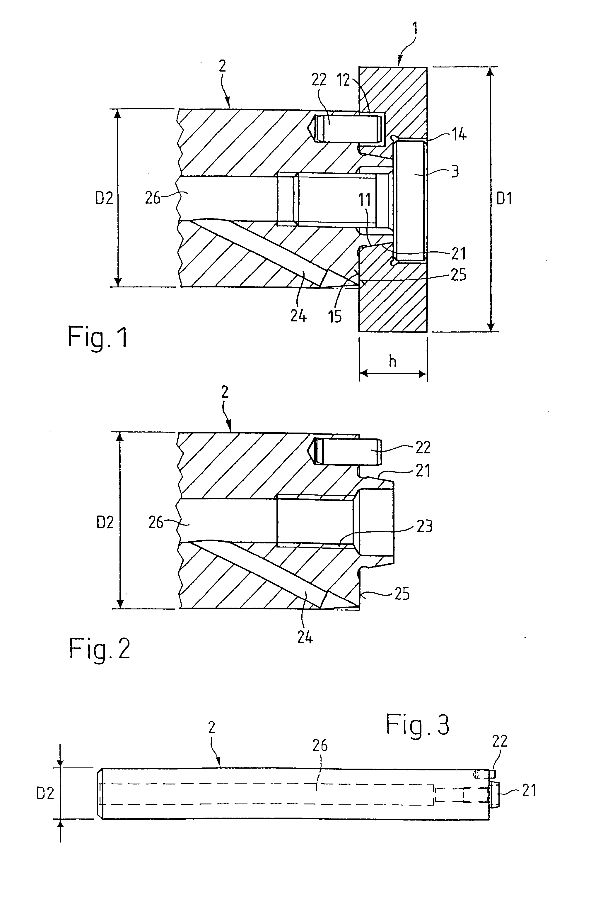
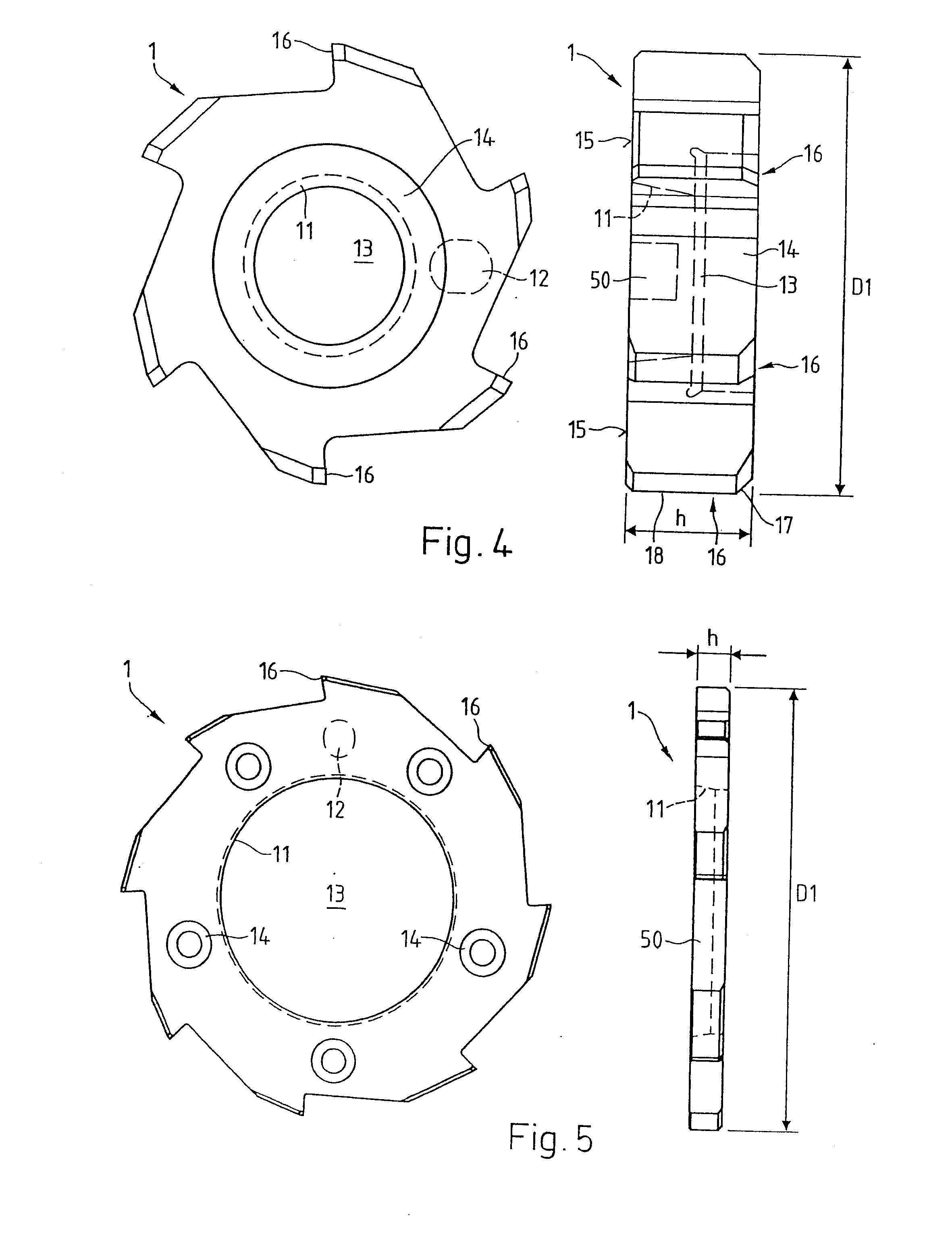
[0018] In a preferred embodiment of the invention, the interchangeable head, as a connection element, comprises a cutout in a plane end-face on the shaft side, for the centering fastening on the shaft. The shaft has no machining means such as teeth or cutters, and has a smaller outer diameter than the interchangeable head. The shaft is preferably of one piece, and on an end-side plane surface comprises a connection lug which projects out of this plane surface in the axial direction and which corresponds to the cutout of the interchangeable head. The interchangeable head thus has no axially projecting lug for exchange adaptation. The material requirement on the interchangeable head is further reduced, and the manufacture of the interchangeable head is simplified by way of this.
[0022] In a preferred embodiment of the invention, the cutout in the end-face of the interchangeable head is a conical socket and accordingly the projecting lug on the shaft is a corresponding conical projection. The dimensions of the conical socket and conical projection are preferably matched to one another such that on placing the interchangeable head onto the shaft, the end-face plane surface of the shaft and the oppositely lying end-side of the interchangeable head have a predefined distance. For fastening the interchangeable head, at least one cap screw is guided through at least one bore in the interchangeable head, and is screwed in the shaft. On tightening the cap screw or the head screws, the conical projection of the shaft is pressed together by the conical socket of the hard interchangeable head, until the end-side plane surface of the shaft and the oppositely lying end-side of the interchangeable head meet one another. A frictional connection arises on account of the pressing-together of these two end-faces. It has been shown that this connection is sufficient for the transmission of torque in normal operation, even with the use of a single, axially centered cap screw. Thus a pure cone connection may be used, without polygonal force transmission means such as triangular or hexagonal connections for example. The manufacture of the interchangeable head as well as of the shaft is simplified by way of this.
[0026] The cylindrical shape of the connection elements on the interchangeable head and shaft permit a simple and inexpensive manufacture, with a sufficient exchange accuracy of the connection.

Problems solved by technology

For this reason, one may only expect a limited accuracy of machining, particularly with the disclosed, relatively thin teeth.
The geometry of the cutting edges—with a negative rake angle—does not however permit any reaming, but a scraping machining at best.

Method used


Image

  • Machine friction tool, interchangeable head and shaft
  • Machine friction tool, interchangeable head and shaft
  • Machine friction tool, interchangeable head and shaft

Examples


Embodiment Construction

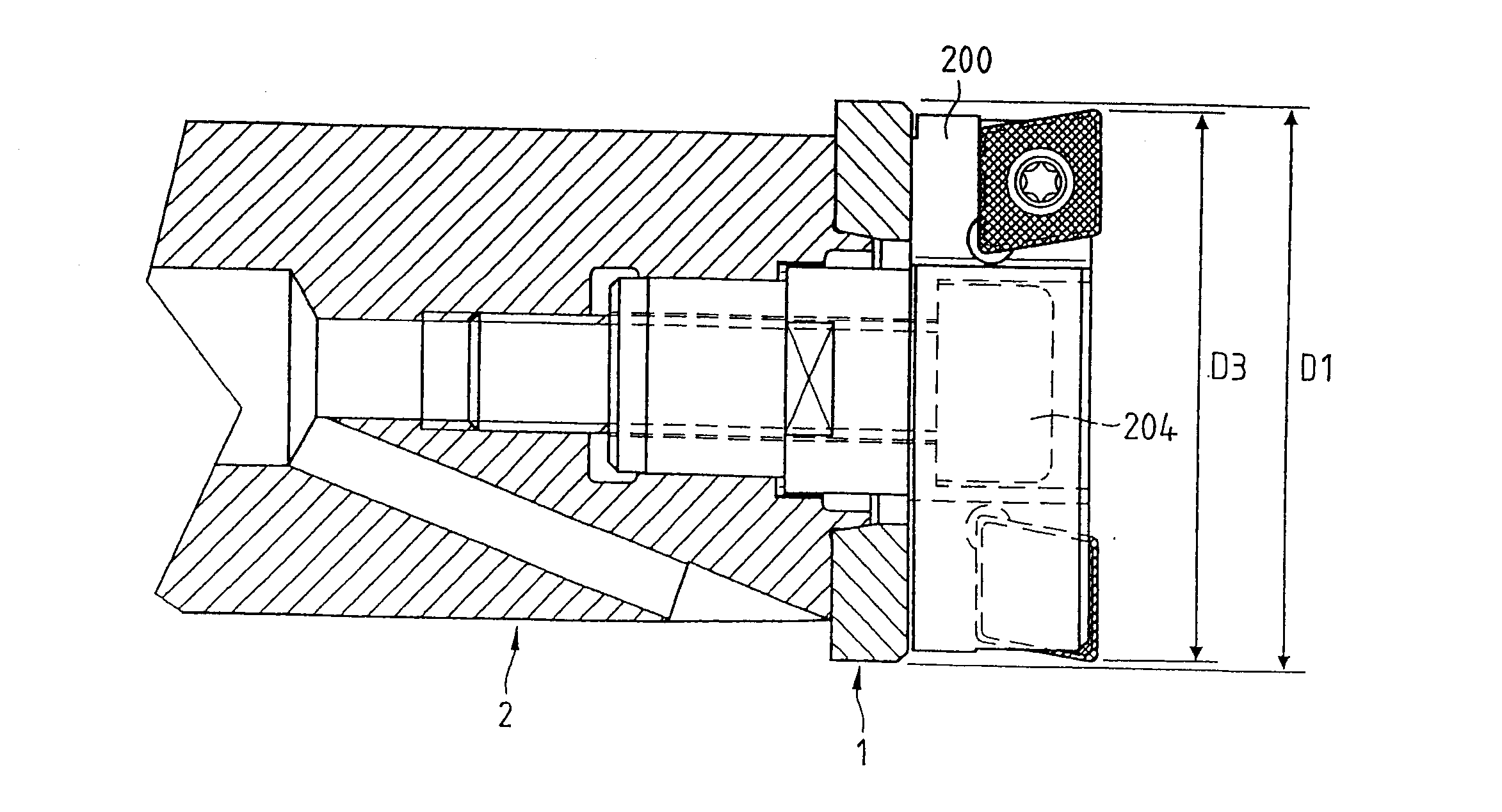
[0064]FIG. 1 shows a longitudinal section through a head region of a machine reaming tool according to the invention. An interchangeable head 1 is screwed onto a shaft 2 by way of a cap screw 3 running centrically in the axial direction. The cap screw 3 is sunk in a pocket 14. The interchangeable head 1 for orientating the interchangeable head 1 in the peripheral direction, comprises an orientation hole 12 and the shaft 2 comprises an orientation pin 22 which projects into the orientation hole 12. The shaft 2 comprises an axial bore 26 from which coolant channels 24 on the tool-side end lead to the outer side of the shaft 2 in the proximity of the interchangeable head 1. An improved cooling of the cutting parts is ensured on account of the proximity of the coolant exit to the interchangeable head 1 and the small thickness h of the interchangeable head. A shaft-side plane surface 15 of the interchangeable head 1 is pressed onto an end-side plane surface 25 of the shaft 2 by way of sc...


PUM

PropertyMeasurementUnit
Lengthaaaaaaaaaa
Thicknessaaaaaaaaaa
Thicknessaaaaaaaaaa

Abstract

A machine reaming tool comprises a reaming head or interchangeable head (1) and a shaft (2), wherein the interchangeable head (1) is of one piece and may be exchanged, and in the axial direction and at each location, thus including means for the exchange adaptation, is thinner than a maximal thickness hmax, wherein this maximal thickness hmax is computed in millimetres from a diameter D1 of the interchangeable head in millimetres as hmax =6 mm+(1 / 10)·(D1−12 mm). On account of this, a guide portion (18) for cutters of the reaming head (1) becomes very much shorter than usual, but despite this ensures an adequate quality of machining. In a preferred embodiment of the invention, the interchangeable head (1) in a plane shaft-side end-face side end-face (15) comprises cutout (11) for the centring fastening on the shaft (2). The shaft (2) on an end-side plane surface (25) comprises a connection lug (21) which projects out of this plane surface in the axial direction and to which the cutout (11) of the interchangeable head (1) corresponds. The interchangeable head (1) thus has no axially projecting lug. The material requirement is further reduced, the manufacture of the interchangeable head (1) is simplified, and the material and manufacturing costs are reduced on account of this.

Description

BACKGROUND OF THE INVENTION [0001] 1. Field of the Invention [0002] The invention relates to a machine reaming tool, to an interchangeable head and to a shaft for a machine reaming tool, as well as to a method for the use of an interchangeable head. [0003] 2. Description of Related Art [0004] Machine reaming tools or machine reamers are used for precision machining cylindrical bores. Individual cutters, in each case, comprise a main cutting edge or leading cut portion, and a secondary cutting edge or guide portion. The leading cut portion performs the material removal work, and the guide portion serves for guiding the tool in the bore. In order to ensure reliable guiding in all machining conditions, for example 10 millimeters or more, with a diameter, for example, of approximately 15millimeters. [0005] A machine reamer is known from WO 01 / 64381 A2 which has a base body and an interchangeable head, that is to say an exchangeable reaming head. The reaming head is formed as one piece a...

Claims


Application Information

Patent Timeline
IPC IPC(8): B23B47/28B23B29/03B23B31/11B23D77/00
CPCB23B31/11Y10T408/906B23B31/1122B23D77/00B23D2277/02B23B29/03Y10T279/16Y10T408/957Y10T29/49996Y10T408/909Y10T408/95Y10T409/30952Y10T408/90993Y10T408/9098Y10T409/309408Y10T408/03B23B31/1107
Inventor ZUMSTEG, GILBERTBERNER, URS
Owner URMA
Learn More