Dissolved air flotation system

a technology of dissolved air and flotation system, which is applied in the direction of multi-stage water/sewage treatment, other chemical processes, separation processes, etc., can solve the problems of hampered use, clear undesirable carcinogenic disinfection by-products, and lack of need given lax water quality standards

Inactive Publication Date: 2005-07-26
SIONIX CORP
View PDF8 Cites 16 Cited by
  • Summary
  • Abstract
  • Description
  • Claims
  • Application Information

AI Technical Summary

Benefits of technology

[0005]The systems and methods described below provide for efficient, modular, transportable dissolved air flotation systems. The system includes a waste transport system that permits continuous operation, entails minimal loss or diversion of influent water for float removal, and provides for easy disposal of waste materials in the float.
[0006]The dissolved air flotation system described below removes 99.99% of particles in the size range of 1 to 10 microns. This represents a 4 to 5 log removal rate. Particles in the 1 to 10 micron size range include prevalent fresh water contaminants such as cryptosporidium (3-5 microns) and giardia (5-7 microns), escherichia coli, and microscopic organic algae and protozoa. The clean effluent may then be treated in conventional disinfectant and filtering systems with greatly reduced load on those systems. Thus, the material requirements for these systems is lower, and the need for injection of chlorine is minimized, along with the deleterious production of toxic disinfectant by-products (voluble organic chemicals) which are the result of chlorine injection into water with high bacterial content. Thus, use of the system will minimize the risk from both microbial pathogens and disinfectant by-products simultaneously.

Problems solved by technology

These carcinogenic disinfection by-products are clearly undesirable.
Though dissolved air flotation is promising as a technique for removing microbes and other suspended solids, its use has been hampered by low volume, lack of need given lax water quality standards, and high cost of installation.

Method used


Image

  • Dissolved air flotation system
  • Dissolved air flotation system
  • Dissolved air flotation system

Examples


Embodiment Construction

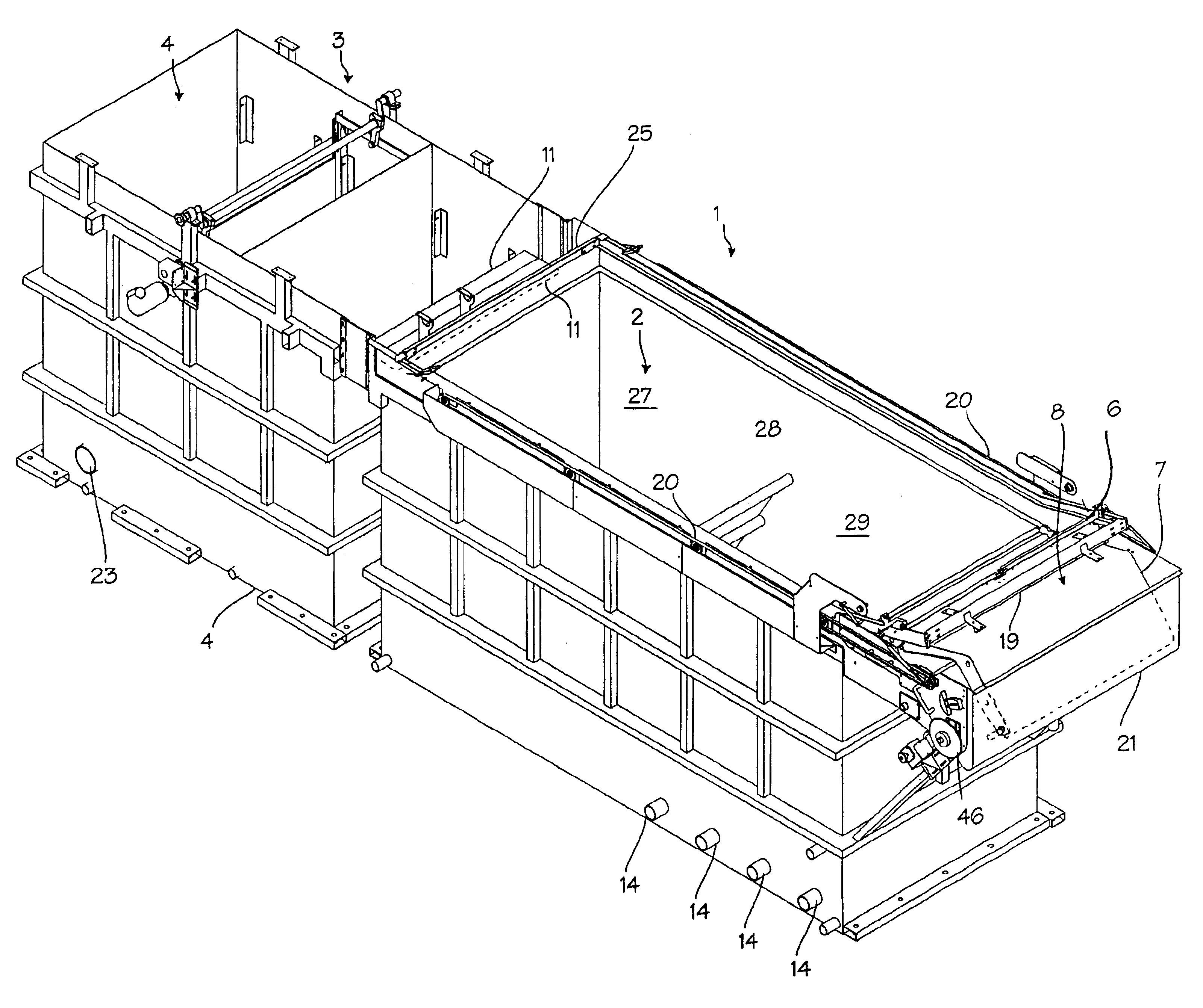
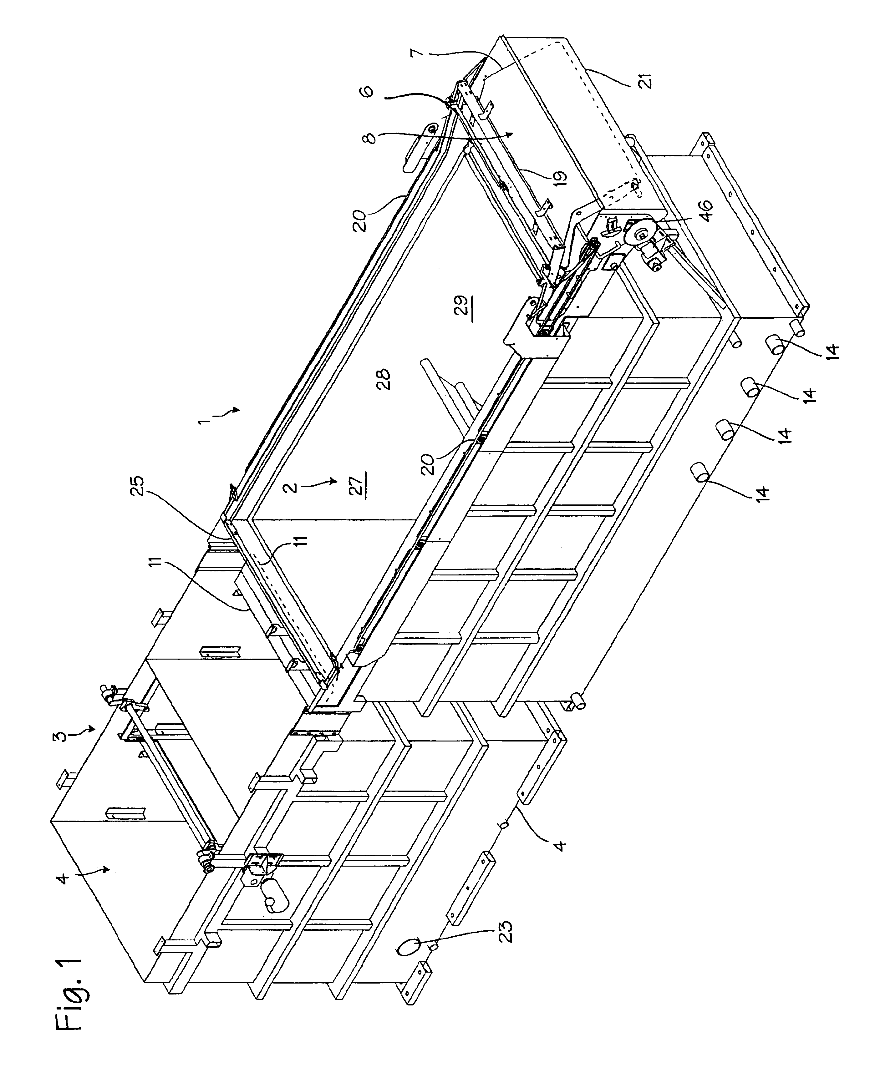
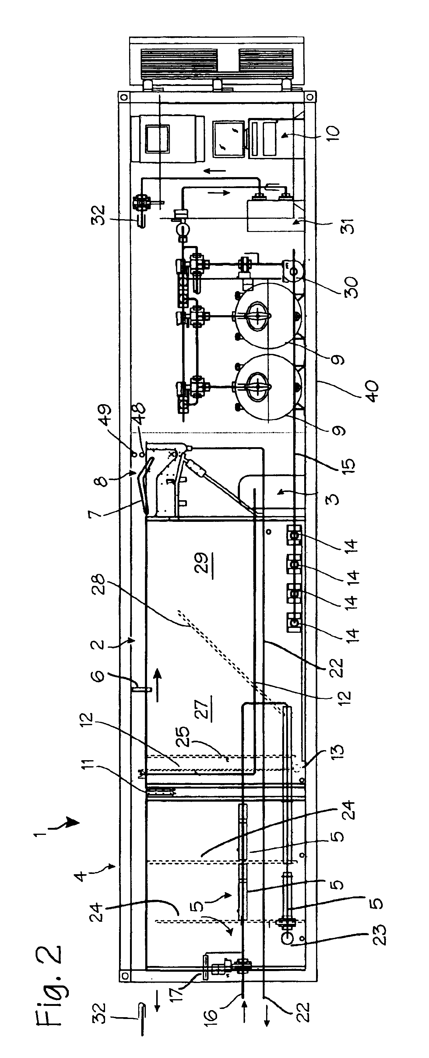
[0011]FIGS. 1 and 2 illustrate the dissolved air flotation system 1. The major components of the dissolved air flotation system include a flotation tank 2 and a dissolved air supply 3, a flocculation tank 4 and influent / coagulant mixing system 5, a skimmer assembly 6, a waste collecting system that includes a beach 7 and waste transport system 8, post-treatment filtration tanks 9, and a control room 10.

[0012]The flotation tank 1 is used to mix influent water with a stream of water containing a large amount of dissolved air. The bubbles produced from the dissolved air attach to flocculent (particles suspended in the water which have aggregated into clumps or masses in the flocculation tank) grown in the influent water and floats to the top of the tank where it collects in a thin layer referred to as float, sludge, or scum. The flotation tank is supplied with unpurified influent from the flocculation tank, flowing over weir 11 (as influent is pumped into the flocculation tank, the flo...


PUM

PropertyMeasurementUnit
sizeaaaaaaaaaa
sizeaaaaaaaaaa
sizeaaaaaaaaaa

Abstract

A dissolved air flotation system and method for purifying fresh water. The system is self-contained within a standard shipping container, with all components disposed in-line within the shipping container. Float is removed from the flotation tank with a skimmer that drives float downstream onto a conveyor belt, and the conveyor belt conveys float away from the flotation tank, in the downstream direction, and deposits the float in a collection tank. Clean water may be drawn from the flotation tank continuously, while float may be removed periodically.

Description

FIELD OF THE INVENTIONS[0001]The inventions described below relate the field of dissolved air flotation.BACKGROUND OF THE INVENTIONS[0002]Dissolved air flotation is one of several processes used to clean and purify water. The process may be used for removing suspended solids, including organisms, from fresh water for municipal water supplies, or for removing suspended solids from industrial wastewater. In the dissolved air flotation process, influent water is mixed with a coagulant to form flocculent particles, and then white water (air-saturated high-pressure water) is injected into a tank of the influent water / flocculent mixture to form air bubbles that attach to the flocculent particles and lift them to the surface. The particles lifted to the surface accumulate in a layer of scum or sludge, referred to as the float. This layer is skimmed off the surface of the tank, while clean water is drawn out of the bottom of the tank.[0003]For municipal water supplies, the suspended solids ...

Claims


Application Information

Patent Timeline
Patent Type & Authority Patents(United States)
IPC IPC(8): B01D21/01B03D1/14
CPCB01D21/01B01D21/08B01D21/2433B03D1/1431B03D1/1462B03D1/247B03D1/028B03D1/082B03D1/1412
Inventor LAMBERT, DAVID P.HOUTZ, JAMES J.
Owner SIONIX CORP
Why Eureka
Try Eureka