

Coupling between a waveguide and a feed line on a carrier plate through a cross-shaped coupling element
a cross-shaped coupling element and waveguide technology, applied in waveguide devices, impedence networks, electrical devices, etc., can solve the problems of high demands on the precision of milling to be carried ou
- Summary
- Abstract
- Description
- Claims
- Application Information
AI Technical Summary
Benefits of technology
Problems solved by technology
Method used
Image

Examples
Embodiment Construction
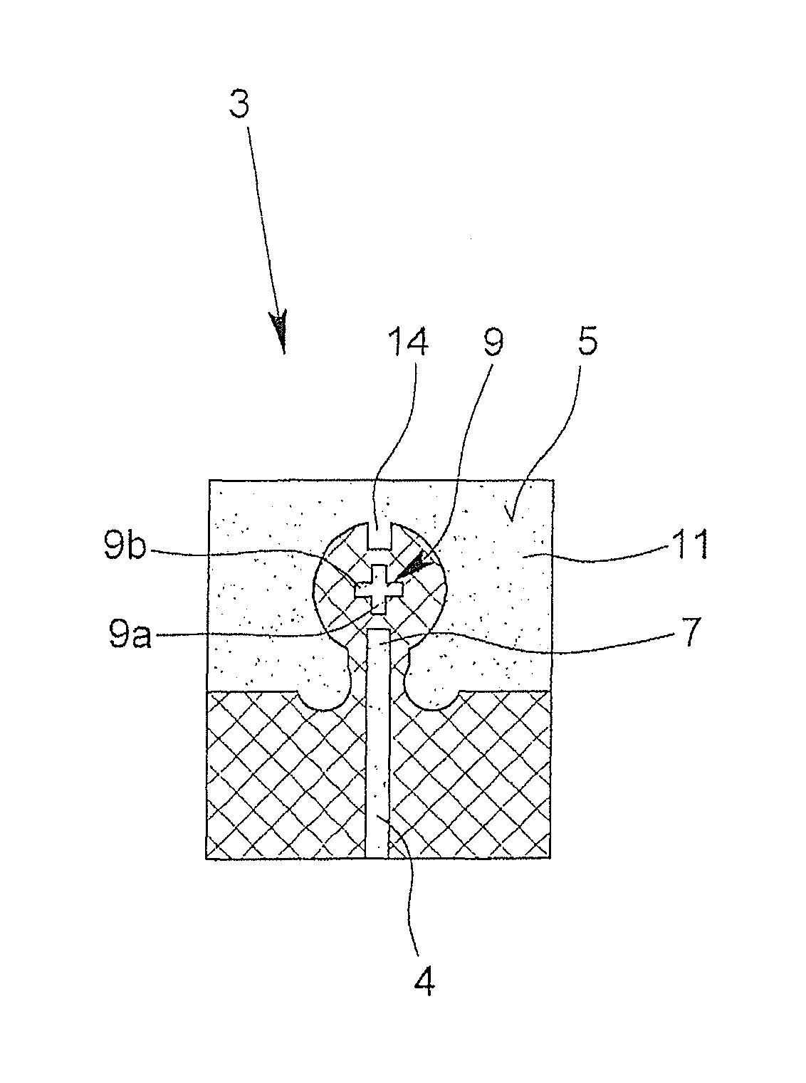
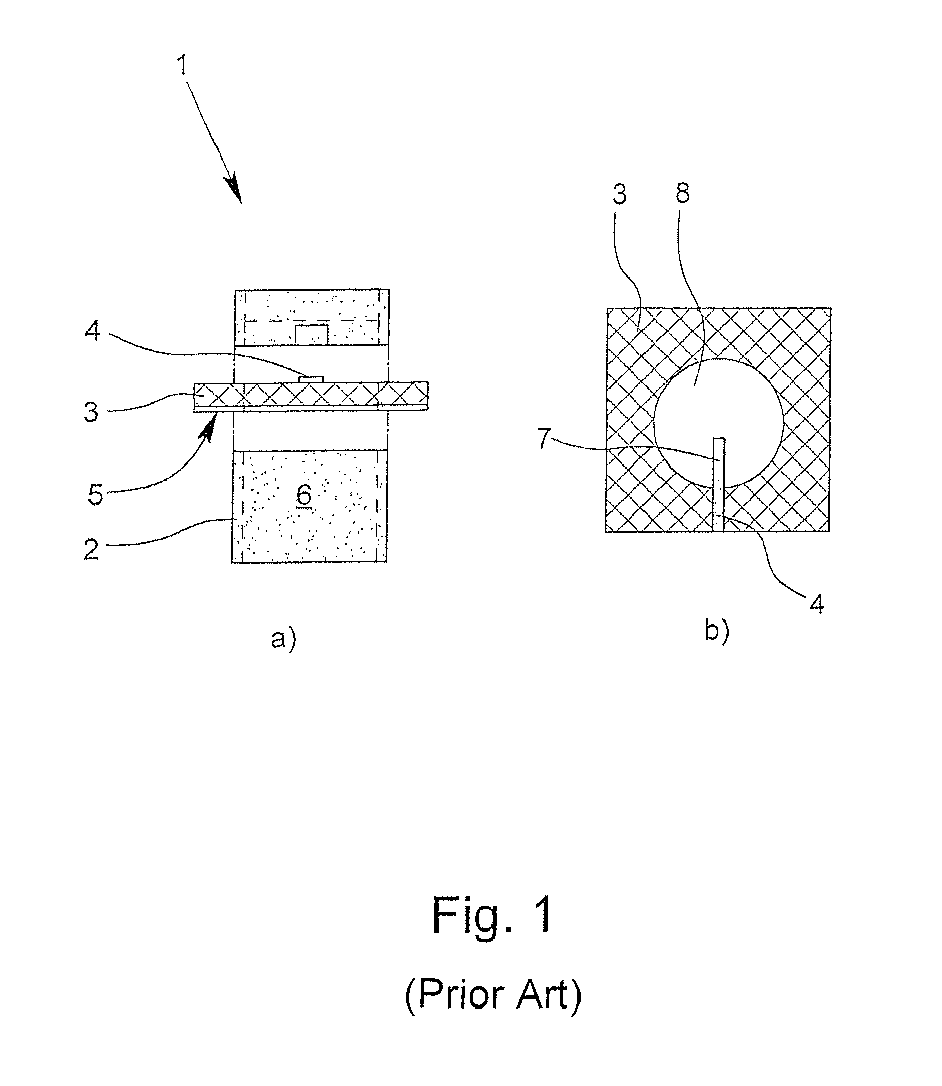
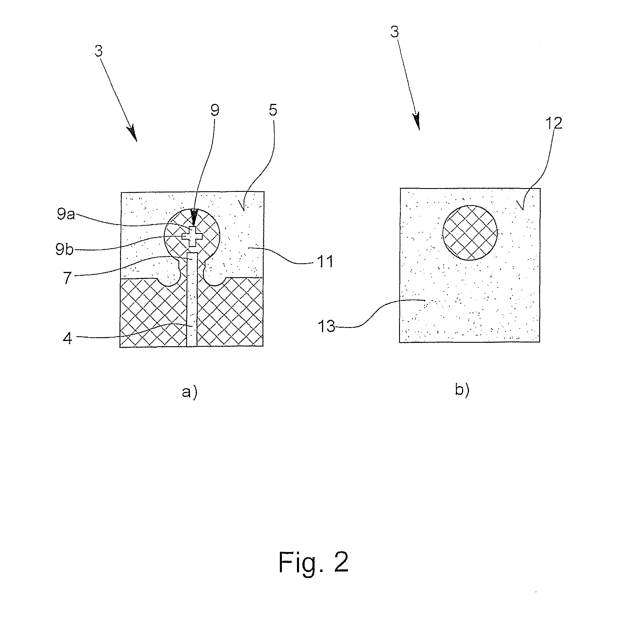
[0024]A waveguide coupling 1 known from the prior art is shown in FIGS. 1a &1b, wherein FIG. 1a shows a waveguide 2, a carrier plate 3 and a feed line 4. The waveguide 2 is placed on the first side 5 of the carrier plate 3 in the mounted state, which is indicated by a dotted line in FIG. 1a.
[0025]The feed line 4 is guided on the carrier plate 3 into the inner area 6 of the waveguide; this is the case at least in the mounted state. The feed line 4 thus terminates with an end 7 (FIG. 1b) in the inner area 6 of the waveguide 2 (FIG. 5), when viewed in the axial direction of the waveguide 2, and thus, is actually provided on an outer end in the irradiation area of the waveguide 2. In FIG. 1b, it can be easily seen that the end 7 of the feed line 4 terminates in the inner area 6 of the waveguide (which is not shown in FIG. 1b) and is uncovered there, namely extends into a milled recess 8. It is easy to imagine that the end 7 of the feed line 4 is complex to produce, and moreover, mechan...
PUM
 Abstract
Description
Claims
Application Information