Tetrahedron beam computed tomography with multiple detectors and/or source arrays

a computed tomography and tetrahedron beam technology, applied in the field of computed tomography (ct), can solve the problems of reducing image quality, poor low contrast differentiation and noisier images, and inferior performance of discrete x-ray detectors that are used, so as to reduce or eliminate beam divergence, reduce the length of source array, and reduce the length of the source array.

Active Publication Date: 2015-03-17
WILLIAM BEAUMONT HOSPITAL
View PDF204 Cites 8 Cited by
  • Summary
  • Abstract
  • Description
  • Claims
  • Application Information

AI Technical Summary

Benefits of technology

[0026]One or more aspects of the present invention provide the advantage of providing a compact volumetric CT system capable of rejecting the majority of scatter photons.
[0027]One or more aspects of the present invention provide the advantage of reducing or eliminating beam divergence so that the field of view can be increased.
[0028]One or more aspects of the present invention provide the advantage of reducing the lengths of source array.
[0029]One or more aspects of the present invention provide the advantage of reducing the lengths of detector arrays.

Problems solved by technology

There are several disadvantages when using CBCT.
The performance of such flat panel detectors, in the aspect of signal-to-noise ratio, detection efficiency and sampling speed, is inferior to discrete x-ray detectors that are used in a diagnostic helical computed tomography scanner.
High noise level and low detection efficiency cause poor low contrast differentiation and noisier images.
A further reduction in image quality may be caused by suboptimal performance of a flat panel imager.
Approximate reconstruction artifacts exist when cone angle is large.
Another disadvantage of CBCT is that when x-ray beams pass through the object 28, x-ray photons are either absorbed or scattered.
Scattered photons will add up on the images, and hence attenuation information cannot be accurately measured.
Scatter causes artifacts in the images.
CBCT images hence have low image quality than those from fan beam CT.
Besides artifacts, scatter contamination also increases noise in the images.
Another problem with such a VCT system is the large cost of a flat panel detector.
However, the length of time the scatter calculation requires can be as long as hours or days using the Monte Carlo method.
Furthermore, the noise from the scatter remains after the scatter profile has been subtracted from the signal, such that the signal-to-noise ratio decreases.
This technique, however, subjects the patient to additional radiation exposure and prolonged scanning time and requires an additional scan to measure the scatter profile.
Further, the noise from the scatter remains, which sacrifices the signal-to-noise ratio.
However, the grid also partially blocks the primary x-ray beams, resulting in additional radiation exposure to the patient.
Because of mechanical limitations, however, the distance from the detector to the patient can be increased only a finite amount.
However, in practice it is difficult to make a large two-dimensional x-ray source array that can provide sufficient field of view.
The two-dimensional x-ray source array is also cumbersome to be used in mobile CT scanners.

Method used


Image

  • Tetrahedron beam computed tomography with multiple detectors and/or source arrays
  • Tetrahedron beam computed tomography with multiple detectors and/or source arrays
  • Tetrahedron beam computed tomography with multiple detectors and/or source arrays

Examples


Embodiment Construction

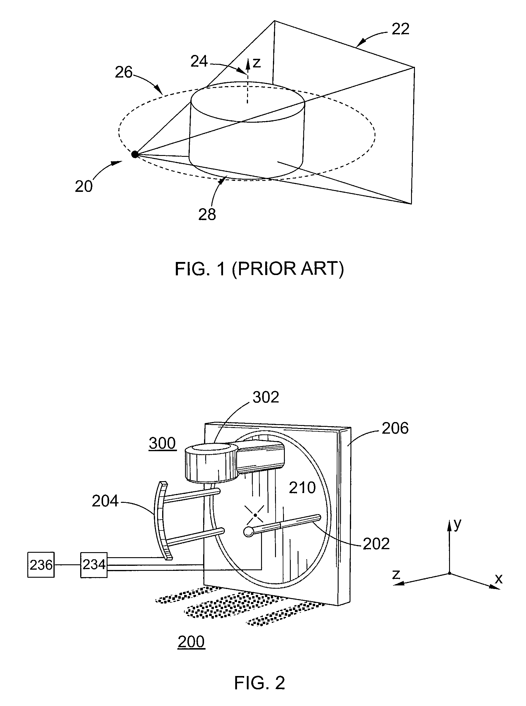
[0044]Referring now to FIGS. 2-12, various imaging systems embodying the principles of the present invention are illustrated, wherein like elements are denoted by like numerals. In particular, FIG. 2 shows an embodiment of a wall-mounted tetrahedron beam computed tomography system 200 and megavoltage portal imaging system 300. The system 200 may be retrofitted onto an existing or new radiation therapy system that includes a separate radiation therapy x-ray source. As shown in FIG. 2, the system 200 includes a separate radiation therapy x-ray source, such as a linear accelerator 302, which is separately mounted to the rotating drum 210. The linear accelerator 302 operates at a power level higher than that of x-ray source 202 so as to allow for treatment of a target volume in a patient lying on movable table (not shown). The table is movable in the x, y and z-directions shown in FIG. 2 via computer 234. The linear accelerator 302 generates a beam of x-rays or particles, such as photon...


PUM


Abstract

A tetrahedron beam computed tomography system including an x ray source array that sequentially emits a plurality of x ray beams at different positions along a scanning direction and a collimator that intercepts the plurality of x-ray beams so that a plurality of fan-shaped x-ray beams emanate from the collimator towards an object. The system includes a first detector receiving a first set of fan-shaped x ray beams after they pass through the object, the first detector generating a first imaging signal for each of the received first set of fan-shaped x-ray beams and a second detector receiving a second set of fan-shaped x ray beams after they pass through the object, the second detector generating a second imaging signal for each of the received second set of fan-shaped x-ray beams. Each detector and source pair form a tetrahedral volume. In other embodiments, the system may also have more than two detectors arrays and / or more than one source array. Each pair of source array and detector array forms a tetrahedral volume. Using multiple detector arrays and source arrays can increase field of view, reduce the length of detector and source arrays so that the imaging system is more compact and mobile.

Description

[0001]The present application is a continuation-in-part application of U.S. patent application Ser. No. 12 / 803,480, filed on Jun. 29, 2010 now U.S. Pat. No. 8,611,490, which is a continuation application of U.S. patent application Ser. No. 11 / 786,781, filed on Apr. 12, 2007, now U.S. Pat. No. 7,760,849, which claims, under 35 U.S.C. §119(e), the benefit of priority of the filing date of Apr. 14, 2006, of U.S. Provisional Patent Application Ser. No. 60 / 792,207, filed on the aforementioned date, the entire contents of each of the above mentioned patent and patent applications are incorporated herein by reference.BACKGROUND OF THE INVENTION[0002]1. Field of the Invention[0003]The present invention relates generally to computed tomography (CT) and, more particularly, to a volumetric computed tomography (VCT) system.[0004]2. Discussion of the Related Art[0005]Computed tomography (CT) provides a transverse image of an object. Conventional fan beam CT uses a point x-ray source and a linear...

Claims


Application Information

Patent Timeline
Patent Type & Authority Patents(United States)
IPC IPC(8): A61B6/03A61B6/00A61B6/02A61B6/06G21K1/02H05G1/70
CPCG21K1/025A61B6/032A61B6/06A61B6/4007A61B6/4028A61B6/4064A61B6/4266A61B6/466A61B6/025A61B6/027A61B6/4441A61B6/4488G21K1/02H05G1/70H01J2235/062H01J2235/068
Inventor ZHANG, TIEZHIXU, XIAOCHAOKIM, JOSHUAYAN, DIMARTINEZ, ALVARO
Owner WILLIAM BEAUMONT HOSPITAL
Why Eureka
Try Eureka