
Unstable monoblock laser cavity with integrated beam expander

a monoblock laser and beam expander technology, applied in the field of lasers, can solve the problems of poor beam quality, heavy and expensive, bulky current laser range finders, etc., and achieve the effects of reducing production labor and material costs, dependable performance, and simplifying manufacturing process

Inactive Publication Date: 2008-09-23
UNITED STATES OF AMERICA
View PDF3 Cites 1 Cited by
  • Summary
  • Abstract
  • Description
  • Claims
  • Application Information

AI Technical Summary

Benefits of technology

The invention is a monoblock laser cavity that improves beam quality. It consists of multiple optical components that share a common optical axis. The output coupler acts as an expanding lens element of a beam expander, which reduces beam divergence. This allows for the use of a smaller diameter optical system to collimate the laser output for use in a laser range finder. The monoblock laser cavity is smaller and more compact than current designs, and it is easier to align and manufacture. It can be used in various applications such as laser range finders and portable and hand-held devices. The invention provides a solution for improving beam quality in a compact laser cavity.

Problems solved by technology

Current fielded laser range finders are bulky, heavy and expensive.
It also allows high order modes of lasing to occur which leads to poor beam quality.

Method used


Image

  • Unstable monoblock laser cavity with integrated beam expander
  • Unstable monoblock laser cavity with integrated beam expander

Examples


Embodiment Construction

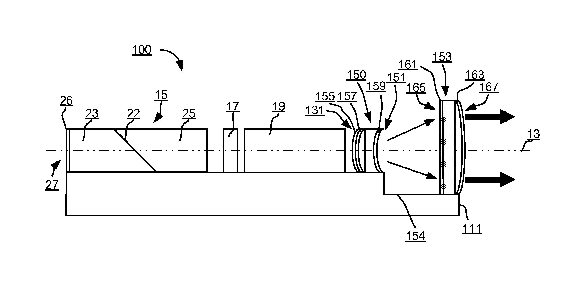
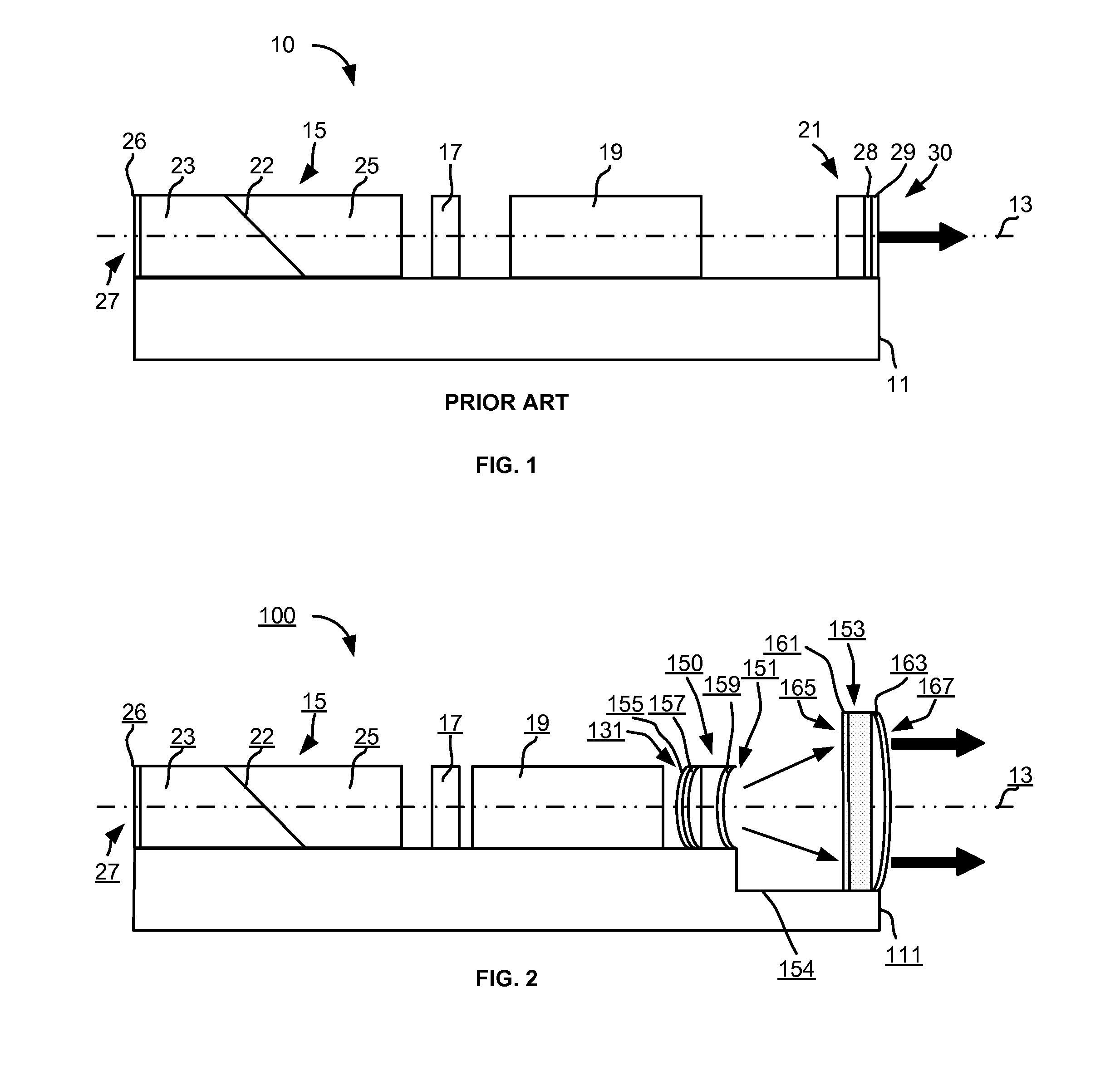
[0022]Referring now to the drawings, FIG. 2 shows a monoblock laser cavity 100 in accordance with the invention. Similar to the monoblock laser cavity 10, the monoblock laser cavity 100 is made up of a plurality of discrete optical elements which are disposed serially on the substrate 111 and share a common optical axis 13. The typical cross-section is square or rectangular, even though it can take various other forms. The optical components are bonded into a “monoblock.” The monoblock laser cavity 100 includes the following optical elements of the monoblock laser cavity 10 described above; the laser rod 15 of gain material, the passive Q-switch 17 and the OPO 19. However, a different output coupler 150, described below in further detail, is used.

[0023]The laser rod 15 has a uniform slit 22 sliced through it at the Brewster angle to the optical axis 13, thus producing two polarizing rod elements 23 and 25 from the single rod of gain material. The high reflector (HR) 26 at the laser ...


PUM


Abstract

A monoblock laser cavity includes a plurality of discrete optical components disposed serially on a substrate and sharing a common optical axis. The optical components include a laser rod of gain material, a Q-switch, an OPO crystal, an output coupler, and a positive lens. The output coupler has a convex input end face and a concave output end face, and acts as the expanding lens element of a beam expander, and the positive lens completes the beam expander to improve the beam quality.

Description

GOVERNMENT INTEREST[0001]The invention described herein may be manufactured, used, sold, imported, and / or licensed by or for the Government of the United States of America.FIELD OF THE INVENTION[0002]The present invention generally relates to lasers, and more particularly, to unstable monoblock laser cavities with integrated beam expanders.BACKGROUND OF THE INVENTION[0003]Laser rangefinders are becoming an increasingly vital component in high precision targeting engagements. The precise and accurate range to target information is an essential variable to the fire control equation of all future soldier weapons. This information is provided easily, and in a timely manner, by laser range finders.[0004]Current fielded laser range finders are bulky, heavy and expensive. These laser range finders were not developed with the individual soldier and his special needs in mind.[0005]The monoblock laser cavity (a laser subassembly, which lacks only an optical pump) described in U.S. Pat. No. 6,...

Claims


Application Information

Patent Timeline
Patent Type & Authority Patents(United States)
IPC IPC(8): H01S3/11
CPCH01S3/025H01S3/0602H01S3/08081H01S3/113H01S3/1083H01S3/07
Inventor NETTLETON, JOHN E.BARR, DALLAS N.
Owner UNITED STATES OF AMERICA
Learn More