

Low sidelobe vortex beam generating method based on multi-ring array
A generation method and low sidelobe technology are applied to antenna arrays, devices for manufacturing antenna arrays, antenna arrays that are powered independently, etc., which can solve the problems of reducing the quality of orbital angular momentum communication and increasing the sidelobe gain of vortex beams. Enhanced integrity, reduced beam divergence angle, and improved communication quality
- Summary
- Abstract
- Description
- Claims
- Application Information
AI Technical Summary
Problems solved by technology
Method used
Image

Examples
Embodiment Construction
[0031] Below in conjunction with accompanying drawing and embodiment, the present invention is described in further detail:
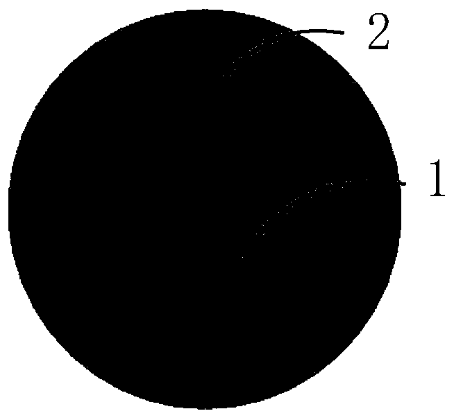
[0032] refer to figure 1 , the multi-ring array used in the present invention includes N concentric ring-shaped arrays, and the i-th ring-shaped array includes M i Microstrip antenna elements uniformly distributed along the circumference, i=1,2,...,N, N≥2, M i+1 ≥ M i ≥4. This embodiment selects but is not limited to N=2 ring-shaped arrays to form a multi-ring array, and the first ring-shaped array 1 and the second ring-shaped array 2 each include eight microstrip antenna units uniformly distributed along the circumference ,M 1 = M 2 =8, the central operating frequency of each microstrip antenna unit is f=3.9GHz.
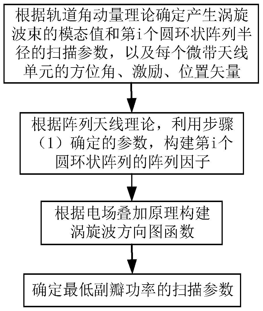
[0033] refer to figure 2 , the present invention is based on the multi-ring array low sidelobe vortex beam generation method, comprising the following steps:
[0034] Step 1, determine the parameters for generating the vortex beam. ...
PUM
 Abstract
Description
Claims
Application Information