Laser lighting lamp

A lighting lamp and laser technology, applied in the field of lighting, can solve the problems of burning out other parts of the laser light source, high heat generation of the laser light source, high heat dissipation requirements, etc., to achieve the effect of increasing the irradiation distance, the long irradiation distance, and reducing the cost of use

Pending Publication Date: 2017-08-18
SUPERVISION LASER TECH SUZHOU CO LTD
View PDF5 Cites 3 Cited by
  • Summary
  • Abstract
  • Description
  • Claims
  • Application Information

AI Technical Summary

Problems solved by technology

However, due to the high heat generation of the laser light source, the heat dissipation requirements are very high. Once the heat dissipation is insufficient, it is easy to cause local overheating, affecting normal use or even burning out the laser light source and other components.

Method used


Image

  • Laser lighting lamp
  • Laser lighting lamp

Examples


Embodiment Construction

[0019] The present invention is described in detail below in conjunction with accompanying drawing:

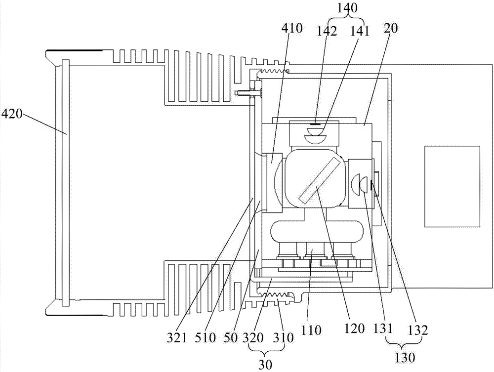
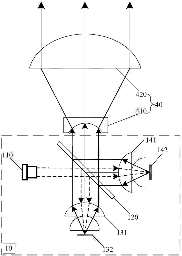
[0020] Such as figure 1 As shown, the present invention provides a laser lighting lamp, including a light emitting unit 10, an installation unit 20 for fixing the light emitting unit 10, and a heat dissipation unit 30 respectively connected to the light emitting unit 10 and the installation unit 20, the The light emitting unit 10 includes a laser source 110, the heat dissipation unit 30 includes a heat dissipation housing 310 sleeved on the outer periphery of the installation unit 20, and a heat conducting member 320 located between the laser source 110 and the heat dissipation housing 310, the light emitting The outgoing beam of the unit 10 exits along the axial direction of the heat dissipation housing 310 , the laser source 110 is located on the side of the mounting unit 20 perpendicular to the outgoing light beam, and the heat conducting member 320 has an L-shaped structur...


PUM


Abstract

The invention discloses a laser lighting lamp. The laser lighting lamp comprises a light-emitting unit, an installation unit used for fixing the light-emitting unit and a cooling unit connected with the light-emitting unit and the installation unit. The light-emitting unit comprises laser sources. The light-emitting unit comprises a cooling shell and a heat conducting piece, wherein the cooling shell is arranged on the periphery of the installation unit and the heat conducting piece is located between the laser sources and the cooling shell. An outgoing beam of the light-emitting unit is emitted out in the axis of the cooling shell. The laser sources are located on the side face, perpendicular to the outgoing beam, of the installation unit. The heat conducting piece is of an L-shaped structure. The laser sources are used as a lighting source, so that the lighting distance and the lighting brightness are greatly improved. Because of the cooling shell arranged on the periphery of the installation unit in a sleeving manner and the L-shaped-structure heat conducting piece located between the laser sources and the cooling shell, heat generated by the laser source can be rapidly conducted outwards to the cooling shell by two edges and are rapidly dissipated, the situation that a local portion is overheated is avoided, and the stability and safety of the product are guaranteed.

Description

technical field [0001] The invention relates to the technical field of lighting, in particular to a laser lighting lamp. Background technique [0002] With the development of semiconductor technology, LED (Light Emitting Diode, light-emitting diode) light source has the advantages of high efficiency, energy saving, environmental protection, low cost and long life, and is gradually replacing traditional incandescent lamps and energy-saving lamps, becoming a general lighting Light source, due to the limitation of the brightness of the current LED light source, there is usually the problem that the central illumination is obviously not enough. In applications such as marine searchlights, stage lighting, car headlights, projection displays, etc. that require ultra-high brightness and long-distance lighting, LED The light source is difficult to meet the requirements. [0003] The laser light source has the advantages of concentrated energy and long irradiation distance, and can ...

Claims


Application Information

Patent Timeline
Patent Type & Authority Applications(China)
IPC IPC(8): F21K9/23F21K9/68F21K9/69F21V13/04F21V29/76F21V29/67F21V29/89F21Y115/30
CPCF21V13/04F21V29/67F21V29/767F21V29/89
Inventor 黄帆龙涛邹诚韩捷飞初宁孙振国
Owner SUPERVISION LASER TECH SUZHOU CO LTD
Why Eureka
Try Eureka