Method and system for detecting vehicle position by employing polarization image

a vehicle position and polarization image technology, applied in scene recognition, instruments, computing, etc., can solve the problems of not being able to directly apply an image to the detection of objects, and the robustness of visible light with regard to various aspects, so as to achieve the effect of rapid generation of the vehicle position

Inactive Publication Date: 2015-03-17
RICOH KK
View PDF11 Cites 1 Cited by
  • Summary
  • Abstract
  • Description
  • Claims
  • Application Information

AI Technical Summary

Benefits of technology

[0013]Furthermore, in the method, the vehicle bottom detecting step comprises a step of extracting candidate wheel pixels by carrying out, based on a predetermined pixel threshold value, binarization with regard to the road surface in the polarization image; a step of performing a smoothing process with regard to the candidate wheel pixels so as to reduce noise; and a step of adopting scan windows, whose size gradually increase in proportion from top to bottom in the polarization image, to scan the whole road surface in the polarization image from top to bottom and left to right, and calculating elements of a co-occurrence matrix corresponding to each of the scan windows so as to determine at least one scan window, whose corresponding co-occurrence matrix has an element whose value is greater than a predetermined threshold value, as the vehicle bottom.
[0018]The method and the system for detecting a vehicle position by employing a polarization image are based on passive detection of the polarized light, using polarization techniques. Therefore, by applying the method and the system, it is possible to rapidly generate the vehicle position. Furthermore, since the polarized light is utilized for carrying out the detection, the method and the system are robust with regard to various lighting conditions, weather, road surface conditions, etc. Moreover, the method and the system may be applied to a vehicle-mounted camera so as to provide a function of preventing collision with another vehicle, and may also be applied to a road monitoring system or an intelligent transport system for detecting a vehicle.

Problems solved by technology

In other words, these kinds of approaches cannot be directly applied to detection of an object in an image.
However, compared to polarized light, the visible light is not robust with regard to various lighting conditions, weather, road surface conditions, etc.

Method used


Image

  • Method and system for detecting vehicle position by employing polarization image
  • Method and system for detecting vehicle position by employing polarization image
  • Method and system for detecting vehicle position by employing polarization image

Examples


first embodiment

[0029]In what follows, a method of detecting a vehicle position by employing a polarization image, according o the present invention is concretely illustrated by referring to FIGS. 1 to 8.

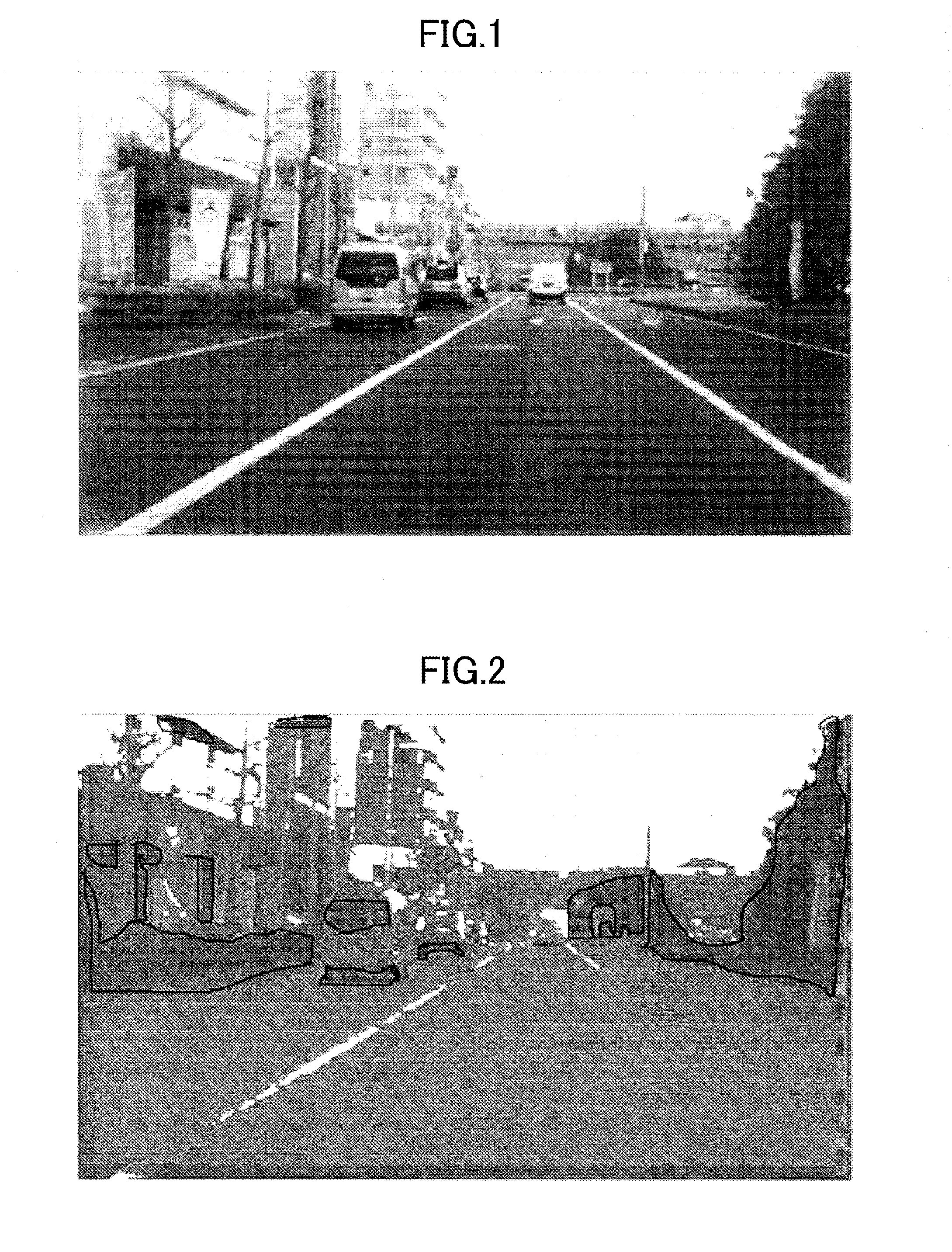
[0030]FIG. 1 illustrates an example of a grayscale image of a road including a few vehicles and background.

[0031]FIG. 2 illustrates a polarization image corresponding to the grayscale image shown in FIG. 1, wherein, parts surrounded by heavy lines are those having different polarized properties. Here it should be noted that different polarized light may also be represented by different color.

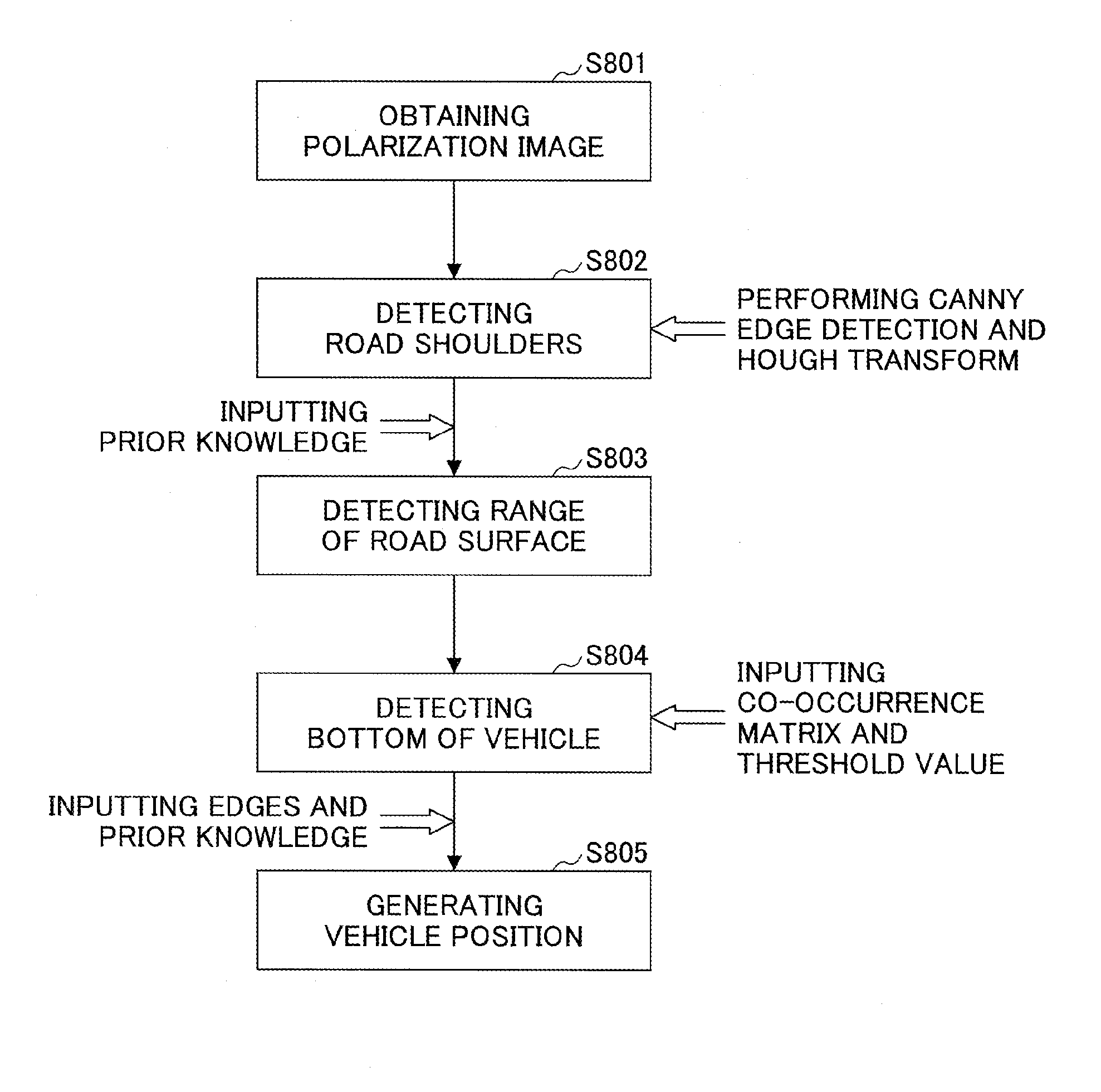
[0032]By taking the polarization image shown in FIG. 2 as an example, a few basic steps of the vehicle position detecting method are described as follows.

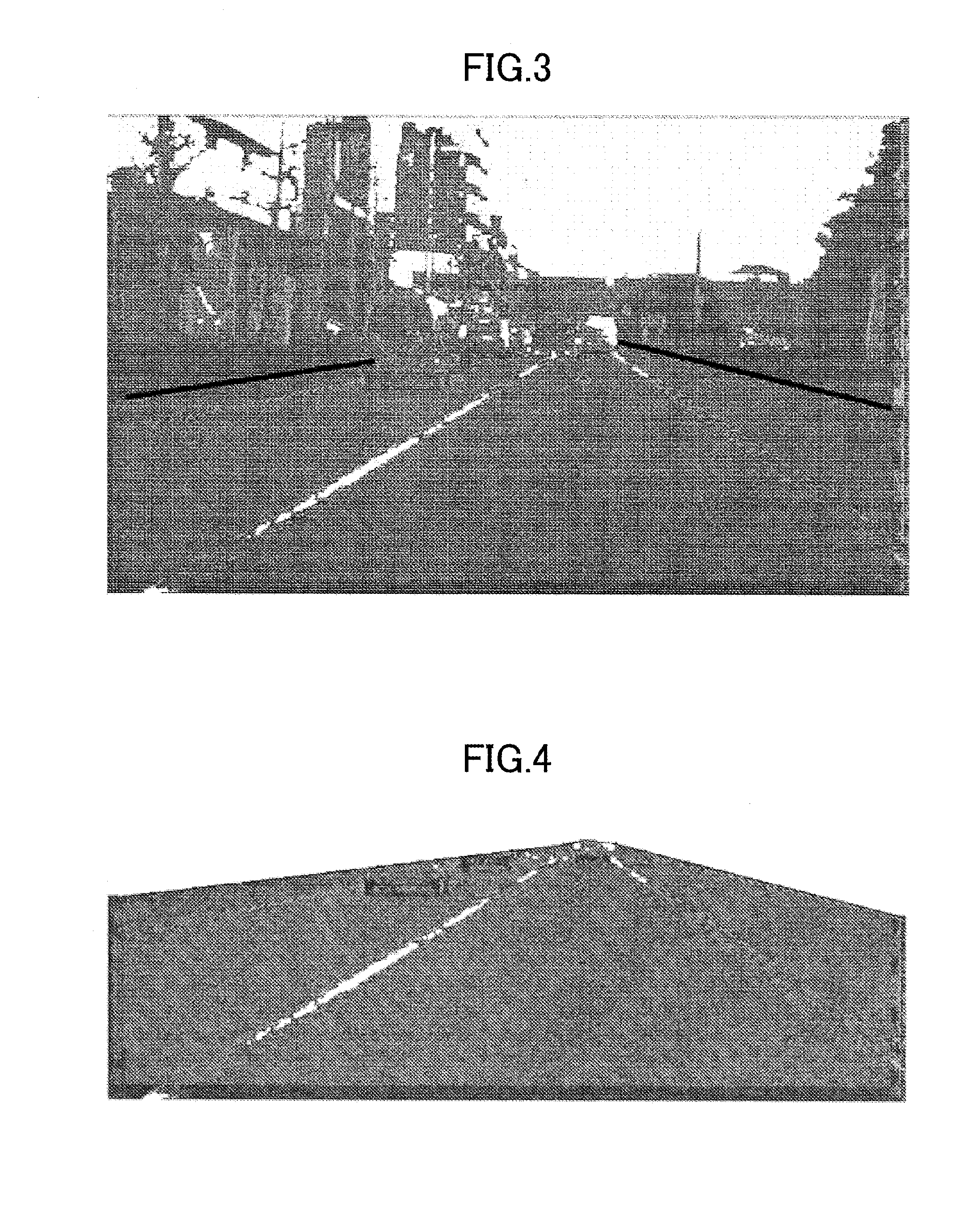
[0033]The basic steps comprise a step of detecting road shoulders on the basis of edges of the polarization image; a step of obtaining a range of a road surface on the basis of the road shoulder information; a step of detecting a bottom region of a vehicle in ...

second embodiment

[0081]In what follows, a system for detecting a vehicle position by employing a polarization image, according to the present invention is concretely illustrated by referring to FIG. 9.

[0082]FIG. 9 illustrates a vehicle detecting system 10 for detecting a vehicle position according to the second embodiment.

[0083]As shown in FIG. 9, the vehicle detecting system 10 includes a first sub system 11 and a second sub system 16. The first sub system 11 includes a road shoulder detecting unit 12, a road surface detecting unit 13, a vehicle bottom detecting unit 14, and a vehicle position generating unit 15. The first sub system 11 utilizes the method according the first embodiment to achieve the vehicle position generation, and outputs the corresponding result. The output result, i.e., the generated vehicle position may be input into a verification system 100 shown in FIG. 9 for verifying whether there is a vehicle at the generated vehicle position, or may be for other use. The second sub sys...


PUM


Abstract

Disclosed are a method and a system for detecting a vehicle position by employing a polarization image. The method comprises a step of capturing a polarization image by using a polarization camera; a step of acquiring two road shoulders in the polarization image based on a difference between a road surface and each of the two road shoulders in the polarization image, and determining a part between the two road shoulders as the road surface; a step of detecting at least one vehicle bottom from the road surface based on a significant pixel value difference between each wheel and the road surface in the polarization image; and a step of generating a vehicle position from the vehicle bottom based on a pixel value difference between a vehicle outline corresponding to the vehicle bottom and background in the polarization image.

Description

BACKGROUND OF THE INVENTION[0001]1. Field of the Invention[0002]The present invention relates to a method and a system for detecting a vehicle position by employing a polarization image.[0003]2. Description of the Related Art[0004]In the fields of vehicle detection, hypothesis generation, polarization, image processing, etc., as a key step of vehicle detection, a hi efficient vehicle position generating approach may extremely increase the detection rate of a whole vehicle detecting system, and may reduce the misrecognition rate thereof.[0005]In the following cited reference No. 1 titled as “A Device For Detection Of Surface Condition Data”, a device for detecting properties or conditions of surfaces like water, snow, ice, etc., is disclosed. Two kinds of reflection are determined by using the following phenomenon: after polarized light is specularly reflected by ice or water on the surface of an object, the polarized nature may be kept, whereas after the polarized light is diffusely...

Claims


Application Information

Patent Timeline
Patent Type & Authority Patents(United States)
IPC IPC(8): G06K9/00
CPCG06K9/00798G06K9/00805G06V20/588G06V20/58
Inventor LIU, TONGSHI, ZHONGCHAOZHONG, CHENGLIU, YUANCHEN, YI
Owner RICOH KK
Why Eureka
Try Eureka