Image forming apparatus

a technology of image forming apparatus and forming plate, which is applied in the direction of electrographic process apparatus, instruments, optics, etc., can solve the problems of insufficient image density, easy generation of toner scattering and insufficient image density, and inability to prevent the generation of white dots

Inactive Publication Date: 2015-03-17
RICOH KK
View PDF67 Cites 1 Cited by
  • Summary
  • Abstract
  • Description
  • Claims
  • Application Information

AI Technical Summary

Problems solved by technology

Thus, as a transfer current flowing through the image of the recording sheet is decreased, a force to retain the toner in the image weakens, and as a result, the toner scattering and the insufficient image density may be easily generated.
However, even though the superimposed bias is used, depending on the exact value of the DC component, the generation of the white dots cannot be prevented sufficiently or the toner scattering and the insufficient image density cannot be prevented sufficiently.
Therefore, the image forming apparatus in this example cannot reliably prevent the generation of the white dots, the toner scattering, and insufficient image density.
It is to be noted that, although the problem caused in a configuration in which the toner image is transferred on the recording sheet in the transfer nip formed between the photoconductor and the transfer roller is described above, alternatively, similar problem occur in the following configuration in the transfer nip formed between an image carrier, such as an intermediate transfer member that is different from the photoconductor, and a nip forming member (secondary transfer nip) that contacts the image carrier, and the toner image on the image carrier is transferred on the recording sheet.

Method used


Image

  • Image forming apparatus
  • Image forming apparatus
  • Image forming apparatus

Examples


experiment 1

[Experiment 1]

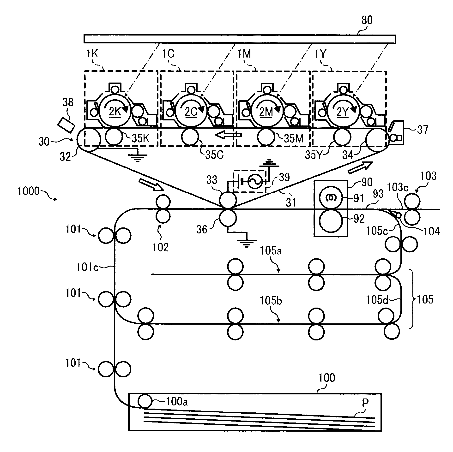
[0102]The inventors prepared a printer having the same configuration as that of the above-described image forming apparatus 1000. The inventors carried out various types of print tests using the printer. In the experiment 1, the process linear velocity is set to 352 [mm / s]. As the recording sheet P, A4 sized paper (wood-free paper, My Paper manufactured by NBS Ricoh) is used.

[0103]In the experiment 1, the single magenta color solid image is formed on the respective first side and the second side of recording medium in the duplex printing mode, under normal experimental laboratory conditions (temperature 23° C. and humidity 50%). At this time, as the DC bias is applied as the transfer bias to both the first side and the second side, the DC bias is gradually increased in a range of from −1 [kV] to −6 [kV] in 0.1 [kV] increments, and the duplex print is performed at the respective voltage values. Then, the magenta single color solid image formed on the second side of the ...

experiment 2

[Experiment 2]

[0108]The toner scattering around the solid image and white dots in the solid image were evaluated under conditions of low temperature and low humidity (temperature: 10° C., humidity: 15%).

[0109]FIG. 5 illustrates the result in the experiment 2. More specifically, FIG. 5 illustrates the relation between the voltage of the secondary transfer bias and the evaluation grade of the white dots and the toner scattering, obtained from the experiment 2. As illustrated in FIG. 5, if focusing on only the toner scattering, by setting the DC bias (absolute value) less than −4.2 [kV], the toner scattering can be evaluated as an acceptable level of grade 4 or 5.

[0110]By contrast, if focusing on only the white dots, by setting the DC bias (absolute value) greater than −5.9 [kV], the white dots can be evaluated as an acceptable level of grade 4 or 5.

[0111]However, the voltage value that fulfills both toner scattering and the white dots over grade 4 does not exist. This is because, at l...

experiment 3

[Experiment 3]

[0113]In the experiment 3, the process linear velocity is set to 352 [mm / s]. As the recording sheet P, A4 sized paper (wood-free paper, My Paper manufactured by NBS Ricoh) is used. The single magenta color solid image is formed on the respective first side and the second side of recording medium in the duplex printing mode, under the ambient in the experimental laboratory is set under conditions of low temperature and low humidity (temperature: 10° C., humidity: 15%)

[0114]As for the power supply 39 to generate a voltage, a function generator (FG300 Yokogawa Electric Corporation) is used to create a waveform, and the voltage is amplified by a factor of 1000 by an amplifier (Trek High Voltage Amplifier Model 10 / 40). As the transfer bias, a superimposed bias in which the AC voltage whose frequency is 500 [Hz] and the peak-to-peak voltage Vpp is 6 [kV] is superimposed on the offset voltage Voff as the DC voltage is used. The superimposed is gradually increased in a range o...


PUM


Abstract

An image forming apparatus including an image forming device, a transfer device, a fixing device, an inverting device, and a processor. The transfer device includes an intermediate transfer member, a nip forming member, and an electric potential difference generator to generate an electric potential difference between the intermediate transfer member and the nip forming member. The processor causes the electric potential difference generator to generate a first electric potential difference containing only a DC component when a toner image is transferred onto a first side of a recording sheet, and to generate a second electric potential difference containing a DC component and a superimposed AC component when the toner image is transferred onto a second side of the recording sheet. The second electric potential difference has an averaged absolute value per unit of time smaller than an absolute value of the first electric potential difference.

Description

CROSS-REFERENCE TO RELATED APPLICATIONS[0001]This patent application is based on and claims priority pursuant to 35 U.S.C. §119 to Japanese Patent Application Nos. 2011-138035, filed on Jun. 22, 2011 and 2012-048153, filed on Mar. 5, 2012 in the Japan Patent Office, the entire disclosures of which are hereby incorporated by reference herein.BACKGROUND[0002]1. Technical Field[0003]The present disclosure relate to an image forming apparatus, such as a copier, a facsimile machine, a printer, or a multi-functional system including a combination thereof to perform duplex printing.[0004]2. Description of the Related Art[0005]Various image forming apparatuses using electrophotographic technology, in which a toner image is formed on a photoconductor, serving as an image carrier, are widely known. The photoconductor contacts a transfer roller, serving as a nip forming member, to form a transfer nip. By applying a transfer bias to the transfer roller, an electric potential difference that ele...

Claims


Application Information

Patent Timeline
Patent Type & Authority Patents(United States)
IPC IPC(8): G03G15/16G03G15/23
CPCG03G15/1605G03G15/234G03G15/1675
Inventor SUGIMOTO, NAOMITANAKA, SHINYA
Owner RICOH KK
Why Eureka
Try Eureka