Marine propulsion device

a propulsion device and a technology for boats, which are applied in the direction of pivots, bearings, shafts and bearings, etc., can solve the problems of increasing the load acting on the crankshaft, increasing the weight of the crankshaft, and the manufacturing cost cannot be kept low, so as to improve the corrosion resistance of the crankshaft, increase the size of the crankshaft, and enhance the strength of the crankshaft

Active Publication Date: 2015-03-24
YAMAHA MOTOR CO LTD
View PDF10 Cites 0 Cited by
  • Summary
  • Abstract
  • Description
  • Claims
  • Application Information

AI Technical Summary

Benefits of technology

[0014]Preferred embodiments of the present invention achieve a reduction in the size of a crankshaft and enhance the reliability and functioning of the crankshaft in a marine propulsion device.
[0016]In the marine propulsion device according to the first preferred embodiment, the entire crankshaft has been processed by the first treatment to at least enhance the corrosion resistance thereof. Therefore, an increase in the size of the crankshaft is prevented, while the strength thereof is enhanced. Further, at least the coupling portion of the crankshaft has been processed by the second treatment to at least enhance the strength thereof. Therefore, it is possible for the coupling portion to obtain a strength so as to endure a load attributed to the high compression within the combustion chambers of the engine. Yet further, the coupling portion is disposed within the crankcase, and is thus isolated from an atmosphere including seawater. Therefore, a corrosion-related problem attributed to seawater is not caused even when the coupling portion is polished or the like after the second treatment in order to obtain a desired accuracy. Furthermore, neither of the first functional portion and the second functional portion, which could be exposed to an atmosphere including seawater, have been processed by the second treatment. Therefore, neither of the first functional portion and the second functional portion is required to be polished or the like after the first treatment. Accordingly, it is possible to enhance the reliabilities and functionalities of the first functional portion and the second functional portion.
[0018]In the marine propulsion device according to the second preferred embodiment, the entire crankshaft has been processed by the first treatment to at least enhance the corrosion resistance thereof. Therefore, an increase in the size of the crankshaft is prevented, while the strength thereof is enhanced. Further, at least the plurality of coupling portions of the crankshaft have been processed by the second treatment to at least enhance the strength thereof. Therefore, it is possible for the plurality of coupling portions to obtain a strength so as to endure a load attributed to high compression within the combustion chambers of the engine. Yet further, the plurality of coupling portions are disposed within the crankcase, and are thus isolated from an atmosphere including seawater. Therefore, a corrosion-related problem attributed to seawater is not caused even when the plurality of coupling portions are polished or the like after the second treatment in order to obtain a desired accuracy. Furthermore, neither of the first functional portion and the second functional portion, which could be exposed to an atmosphere including seawater, has been processed by the second treatment. Therefore, neither of the first functional portion and the second functional portion is required to be polished or the like after the first treatment. Accordingly, it is possible to enhance the reliabilities and functionalities of the first functional portion and the second functional portion.

Problems solved by technology

However, a load acting on a crankshaft is increased due to such high compression.
Therefore, the manufacturing cost cannot be necessarily kept low.
However, enlarging the size and shape of a crankshaft results in an increase in the weight of the crankshaft.
Under this condition, it is difficult to enlarge the engine cover and still reliably produce adequate steering ranges for adjacent outboard motors.
Thus, it is also not easy to enlarge the engine itself.
In view of this, it is also difficult to enlarge the size and shape of the crankshaft.
However, it is insufficient to perform only the soft nitriding treatment to obtain a strength required for a crankshaft in which high compression is achieved within the combustion chambers.
In this case, however, the crankshaft is greatly affected and thermally expanded by the induction hardening treatment.
Thus, the number of manufacturing steps is inevitably increased as a whole.
When an induction hardening treatment is performed on the entire crankshaft including the functional portion, thermal expansion is caused due to the induction hardening treatment.
Thermal expansion produces a drawback in that the accuracy in the axial center of the functional portion is degraded and the function of the functional portion is deteriorated.
When the nitride layer is eliminated through the polishing treatment, a drawback is produced in that the functional portion loses a corrosive-resistant function.
Therefore, in terms of corrosion resistance, deterioration in the function of the functional portion is also inevitably caused by executing the induction hardening treatment on the entire crankshaft.
Therefore, a drawback is produced similarly to the above.

Method used


Image

  • Marine propulsion device
  • Marine propulsion device
  • Marine propulsion device

Examples


Embodiment Construction

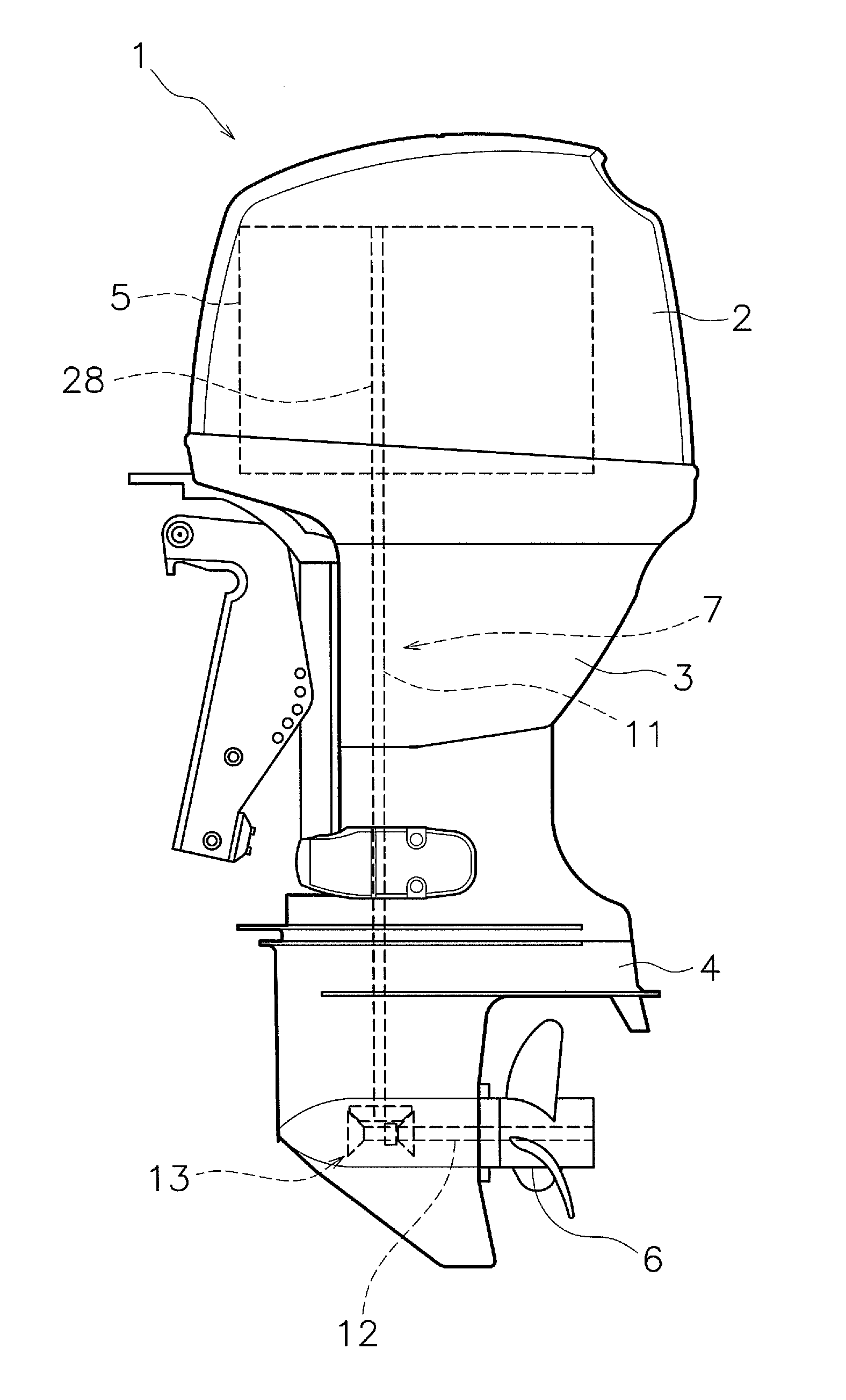
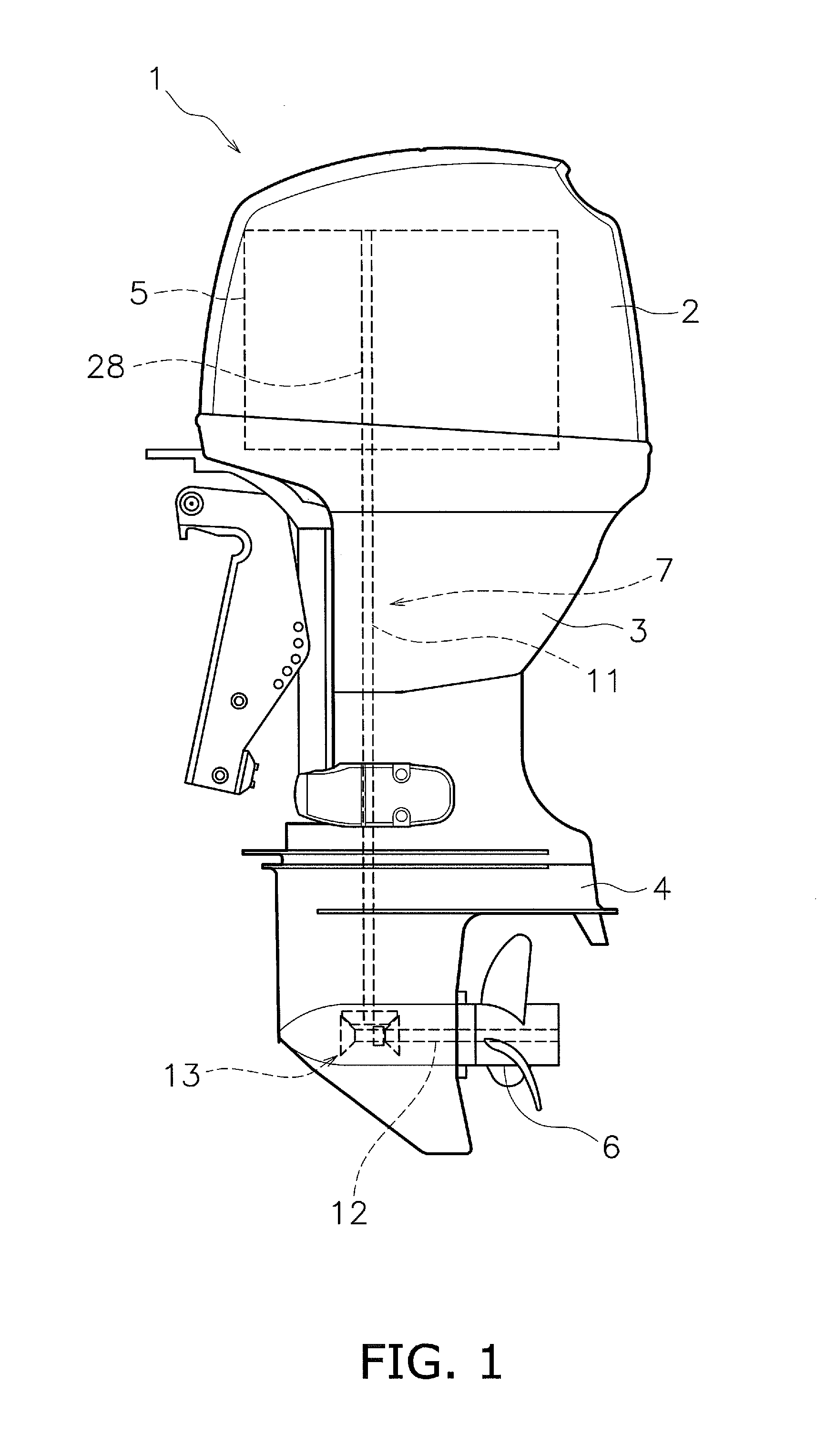
[0024]Explanation will be hereinafter provided for a marine propulsion device 1 according to exemplary preferred embodiments of the present invention with reference to the attached drawings. FIG. 1 is a side view of the marine propulsion device 1. The marine propulsion device 1 includes an engine cover 2, an upper casing 3, and a lower casing 4. The upper casing 3 is disposed below the engine cover 2. The lower casing 4 is disposed below the upper casing 3. The marine propulsion device 1 includes an engine 5, a propeller 6, and a power transmission mechanism 7. The engine 5 is disposed in the upper portion of the marine propulsion device 1. The engine 5 is disposed within the engine cover 2. The propeller 6 is disposed in the lower portion of the marine propulsion device 1. The propeller 6 is attached to the lower casing 4. The propeller 6 is configured to be driven and rotated by a driving force of the engine 5.

[0025]The power transmission mechanism 7 is configured to transmit the ...


PUM


Abstract

A crankshaft includes a coupling portion, a first functional portion, and a second functional portion. The coupling portion is coupled to a connecting rod. The first functional portion is provided on an upper portion of the crankshaft protruding from a crankcase. The first functional portion drives a first functional component. The second functional portion is provided on a lower portion of the crankshaft protruding from the crankcase. The second functional portion drives a second functional component. The entire crankshaft has been processed by a first treatment to at least enhance the corrosion resistance thereof. At least a coupling portion of the crankshaft has been processed by a second treatment to at least enhance the strength thereof. Neither of the first functional portion and the second functional portion has been processed by the second treatment.

Description

CROSS-REFERENCE TO RELATED APPLICATIONS[0001]This application claims priority to Japanese Patent Application No. 2012-275667 filed on Dec. 18, 2012, which is hereby incorporated by reference in its entirety.BACKGROUND OF THE INVENTION[0002]1. Field of the Invention[0003]The present invention relates to a marine propulsion device.[0004]2. Description of the Related Art[0005]To reduce fuel consumption, marine propulsion devices such as outboard motors have been demanded to achieve high compression within the combustion chambers of an engine. However, a load acting on a crankshaft is increased due to such high compression.[0006]In Japan Laid-open Patent Application Publication No. JP-A-S62-165014, axial support portions (journals) of a crankshaft, which are required to be durable, are made of a material with a durability higher than that of the other portions. The axial support portions are connected to the other portions by welding. JP-A-S62-165014 discloses that the fatigue strength ...

Claims


Application Information

Patent Timeline
Patent Type & Authority Patents(United States)
IPC IPC(8): F02B75/32F02B61/04
CPCF02B61/045Y10T74/2173Y10T74/2183
Inventor KUROIWA, MAKOTONARUSE, ISAMUMIYAZAKI, SATOSHIKANEKO, HIROKAZU
Owner YAMAHA MOTOR CO LTD
Why Eureka
Try Eureka