Wall mounting apparatus and frame assembly

a wall mounting and frame assembly technology, applied in the direction of containers, transmissions, building components, etc., can solve the problem of laborious attachment of boxes to wall substrates, and achieve the effect of strengthening the structur

Active Publication Date: 2015-03-24
BRAINWAVE RES CORP
View PDF34 Cites 16 Cited by
  • Summary
  • Abstract
  • Description
  • Claims
  • Application Information

AI Technical Summary

Benefits of technology

[0006]The needs described above are fulfilled, at least in part, by use of a self-supporting apparatus that can be placed in a pre-set opening in an existing wall substrate. A frame is configured with a perimeter edge that corresponds to the thickness of the wall substrate. The edge of the frame thus can be in fitting contact with the substrate opening. Flanges on opposite sides of the frame extend in the planar direction of the wall substrate to be in contact with the inner and outer surfaces of the substrate to maintain the frame in position in the wall and to strengthen the structure. The frame can include appropriate mounting portions for mounting electrical boxes or low voltage device within the wall.
[0013]In an alternative arrangement, the frame may comprise an interlocking hinge structure on opposite sides. Inward pressure on the sides of the frame with consequent inward bending of the sides will cause the height of the frame to contract. The frame will then have sufficient clearance for easy insert in the wall opening. Upon release of the bending pressure, the height of the frame returns to its heightened state for a tight fit with the wall opening contour. In lieu of a hinged structure, the frame may be comprised of an elastomeric material for reducing the frame dimension when compressed and returning the frame to its normal position by when expanded.
[0017]Frames may be formed of integral material with perimeters corresponding in dimension with the wall opening. With elastomeric flanges extending from only one side of the frame, the frame can be inserted by placing that side in contact with the corresponding wall opening portion, the flanges extending on inner surfaces of the wall. The frame can then be wedged into the opening by pivoting the frame about the side already in contact with the wall opening. Retainers can then be adjusted to maintain and strengthen the frame installation.
[0019]A groove in each frame portion may be located to define a passively biased resting position when engaged with a detent in the opposed frame portion. The bracket assembly then assumes a compressed bracket assembly state. The groove may terminate in a ramp configuration to facilitate disengagement of the detent when the assembly is to be expanded for mounting in the wall opening. A second groove in each frame portion is located distally from the first groove for locking engagement with the detent to define an expanded bracket assembly state. The perimeter of the engaged frame portions in the expanded state conform to the wall opening perimeter. An outwardly extending tab in the vicinity of each detent facilitates unlocking engagement of the detent from the second groove to release the assembly from its expanded state. Manual pressure on the tabs of each frame portion in a direction toward one another can free the engagement.
[0020]Inadvertent detachment of the frame portions beyond the expanded state of the bracket assembly may be avoided by provision of a tooth portion extending from the inner surface of the first side of each frame portion and a barb extending from the outer surface of the second side of each frame portion. Further expansion of the assembly is curtailed by abutment between the barbs and tooth portions.
[0021]At least one flange extends from a surface of the cross member for contact with the wall surface when the assembly is mounted within the opening. A plurality of flanges, spaced from each other in a direction of the thickness of the wall, may extend from each of the frame portion cross members for contact with the outer and inner surfaces, respectively, of the building wall. Spikes may face outwardly from a flange surface near corners. Temporary contact of the spikes with a wall surface can determine the periphery of the wall opening to be formed. Such contact can be made with the bracket assembly in its compressed state. An inwardly protruding rib can be formed on a flange to provide lateral stability of the assembly in the wall.

Problems solved by technology

The electrical box or low voltage device must be securely attached to the wall substrate as there is no readily available opportunity to mount the box to a closed wall stud.
Attachment of the box to the wall substrate is labor intensive.

Method used


Image

  • Wall mounting apparatus and frame assembly
  • Wall mounting apparatus and frame assembly
  • Wall mounting apparatus and frame assembly

Examples


Embodiment Construction

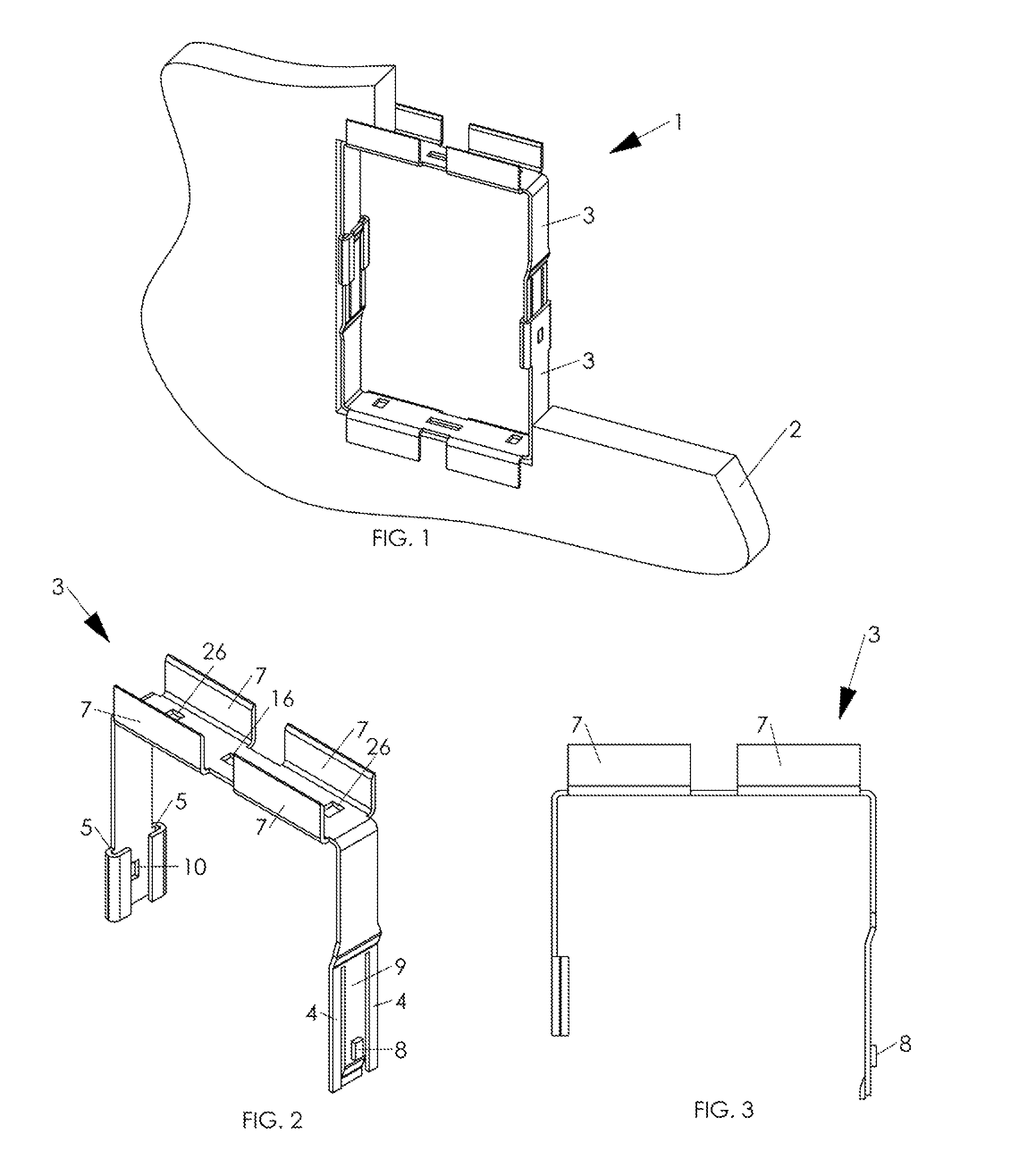
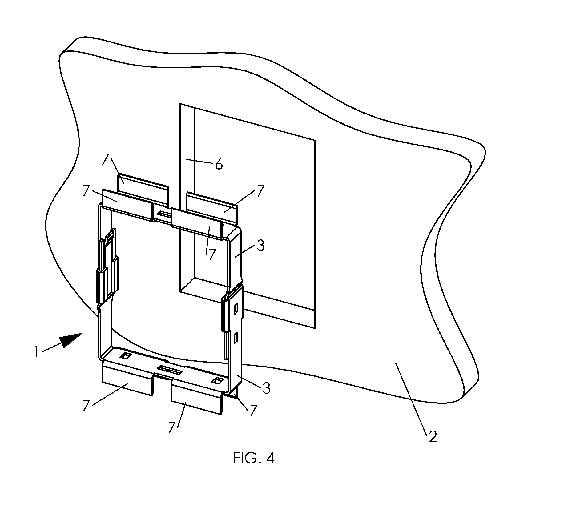
[0103]In FIG. 1, frame assembly 1 is shown mounted in a cut away sheet of drywall 2. The drywall opening can be prepared with a drywall saw. The frame assembly comprises two frame elements 3 that together can be adjusted to define a perimeter that fits the contour of the drywall opening. The depth of the frame corresponds to the depth of the drywall.

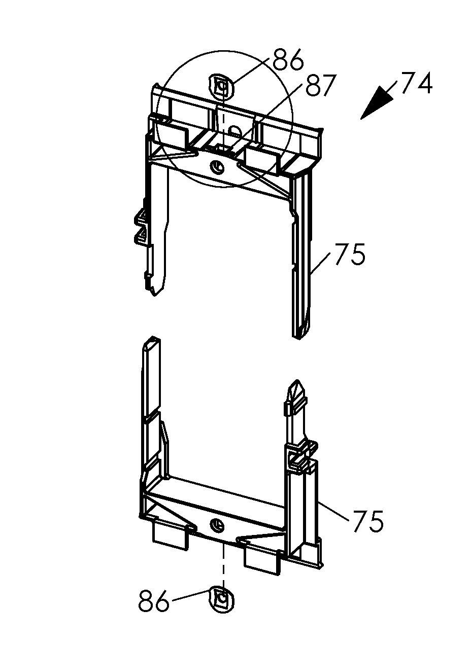
[0104]Both frame elements may be identical, as represented more particularly be a frame element perspective view in FIG. 2 and an elevation view in FIG. 3. For clarity of illustration, only the upper frame element 3 of FIG. 1 is shown. Frame element 3, of U-shaped configuration, can be stamped and formed out of metal, for example, galvanized sheet metal. Of course, any other suitable material can be used to form the frame elements. Flanges 7 extend upwardly from the top edges of frame element 3. The frame element sides are of unequal length. The shorter side terminates in a track channel 5. Aperture 10 is formed in the side of the frame ...


PUM


Abstract

A self-supporting apparatus can be placed in an opening in an existing wall substrate. A frame assembly is configured with a perimeter that can be adjusted to correspond to the opening of the wall substrate. Opposing frame portions are movable in opposite directions with respect to each other to be expandable for contact with the opening. Each frame portion comprises a first side having a detent on one surface and a second side with at least one groove on a surface thereof. The surfaces of the opposing frame portions face each other. The detents and grooves are dimensioned to provide engagement, respectively, between grooves and dents of facing frame portion surfaces.

Description

[0001]This is a continuation-in-part of application Ser. No. 13 / 101,758, filed May 5, 2011 on behalf of inventors Guy Gagne and James Rogers. The benefit of provisional application 61 / 550,085, filed Oct. 21, 2011 on behalf of Guy and James Rogers, is claimed under 35 U.S.C. 119(e).BACKGROUND[0002]This disclosure is related to installation of electrical components in building structures, more particularly, to installation of electrical boxes, low voltage devices and the like in existing building walls.[0003]Electrical switches and receptacles require electrical boxes to meet existing electrical codes. In new house or building construction, boxes typically are attached to wall studs or joists before drywall or equivalent sheet material is applied to enclose the wall space. Openings can be cut in the sheet material to accommodate the boxes to be mounted in known positions.[0004]For retrofitting applications that require addition of electrical or low voltage device access to pre-existin...

Claims


Application Information

Patent Timeline
Patent Type & Authority Patents(United States)
IPC IPC(8): B65D8/18H02G3/12H02G3/14H02G3/36H04B1/38
CPCH02G3/121H02G3/36H04B1/38H02G3/123H02G3/14H02G3/125H02G3/126
Inventor GAGNE, JEAN-GUYROGERS, JAMES W.
Owner BRAINWAVE RES CORP
Why Eureka
Try Eureka