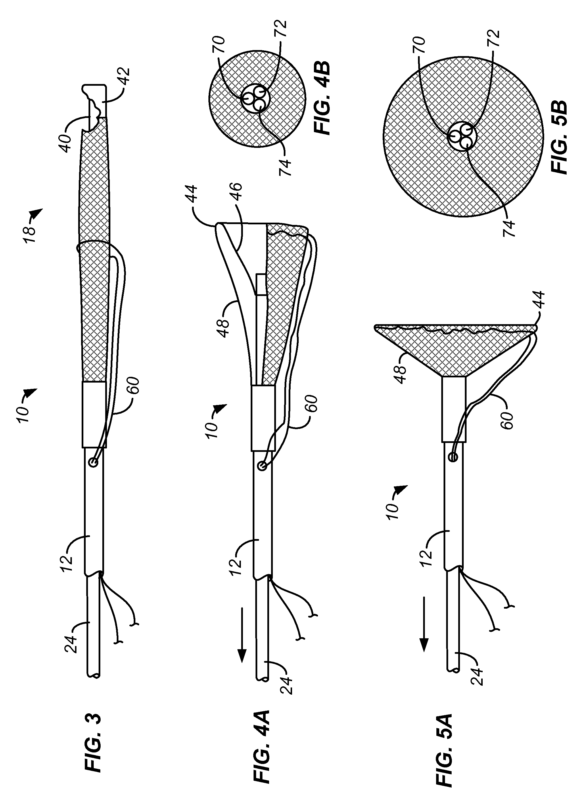
[0011]During delivery and prior to deployment, the perforate sweeping structure is usually maintained in a tubular configuration. Such a tubular structure may be deployed by axial foreshortening. The sweeping structure is disposed over a distal portion of the viewing scope, where the tubular configuration is transformed into a concave structure which extends distally from the distal end of the viewing scope. The concave structure, which may be conical, hemispherical, or have other expansibly tapered structures, will surround the optical element of the viewing scope so that view from the element is not obscured. Moreover, the tubular configuration of the sweeping structure will typically be sufficiently flexible so that the distal end or region of the viewing scope can be steered in a conventional manner without excessive constraint by the sweeping structure. When the tubular configuration of the sweeping structure is shifted to the concave structure, however, it will become more rigid, allowing it to engage, move, and entrap kidney stones against the body cavity wall while retaining sufficient flexibility to conform to an irregularly shaped wall surface. While a preferred perforate sweeping structure is deployed by foreshortening, alternative sweeping structures may have an initial collapsed, closed configuration extending over the distal end of the viewing structure and may be deployed or otherwise opened to a concave configuration surrounding the distal end of the viewing structure, typically by releasing the constrained structure from a surrounding sleeve or other structure.
[0012]The methods of the present invention optionally include steering the viewing scope within the body cavity while the distal portion of the viewing scope is present within the tubular configuration of the sweeping structure. Methods further comprise engaging the perforate structure against the urinary stones when said structure is sufficiently rigid to manipulate the stones while remaining sufficiently flexible to conform an outer rim of the structure to an irregularly shaped bladder wall and sufficiently porous to allow fluids to pass freely through the perforations or apertures in the perforate structure when the region is being irrigated. Generally, the perforate sweeping structure will be formed as a metal or polymeric mesh with individual interwoven wires or filaments. The mesh will have openings or interstices which are sufficiently large to allow the free flow of irrigation fluid, but which have dimensions which contain and / or entrap the stone fragments within the mesh, particularly within a double walled mesh structure which will be described hereinbelow. Usually, porosity of the deployed perforate structure will be sufficient to limit stones larger than 2 mm in any dimension from passing therethrough. The deployed perforate structure utilizes irrigation from the viewing scope to maintain the captured stone fragments (typically smaller than 2 mm) against the interior of the perforate structure and / or against the wall of the body cavity so as not to obscure vision during lithotripsy procedures.
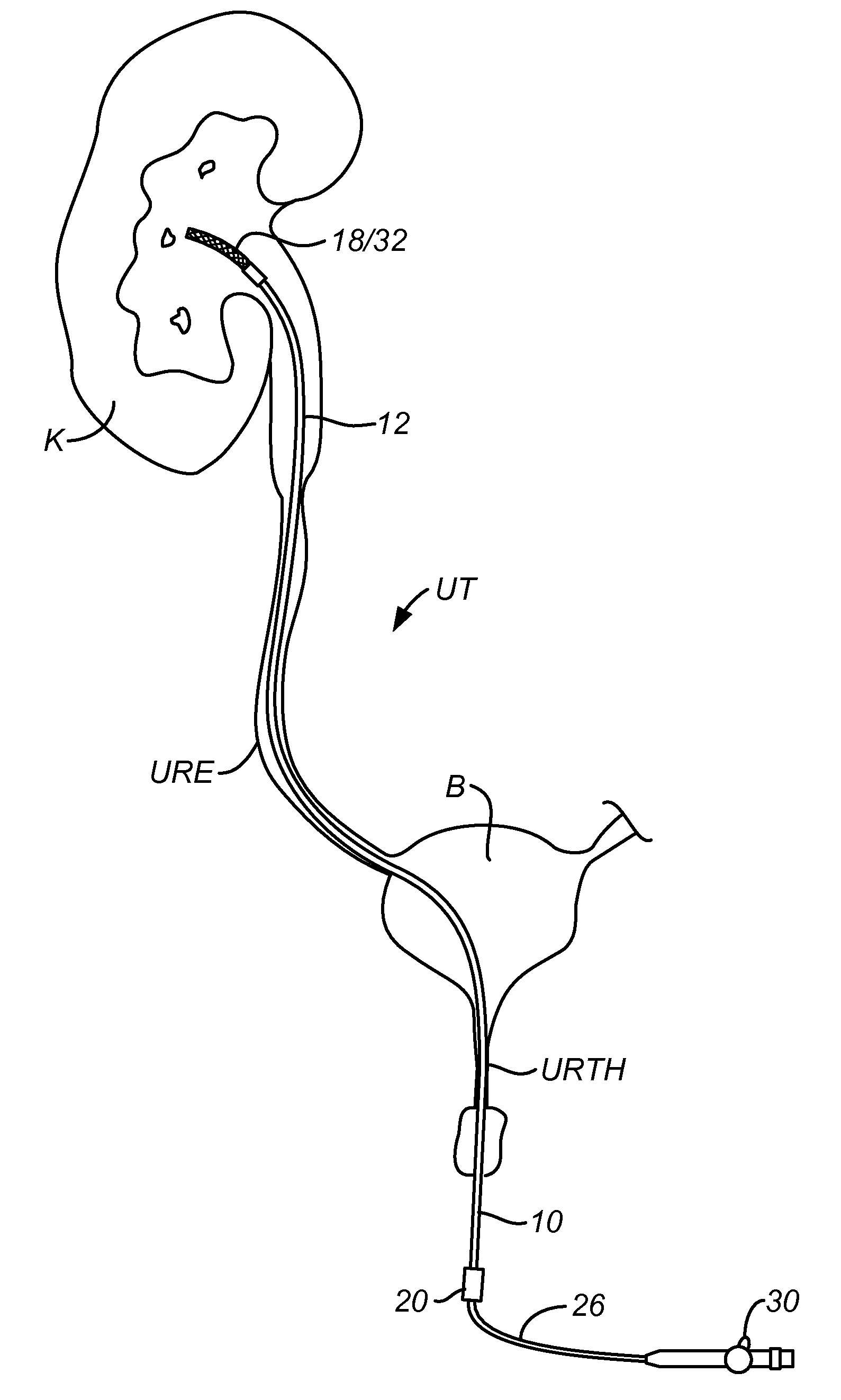
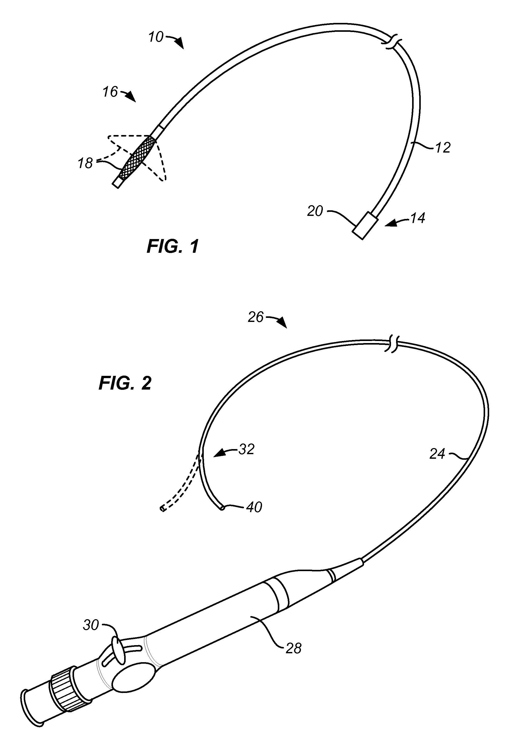
[0016]The perforate sweeping structure will be removably attached to and extend distally from the distal end of the sheath. The perforate sweeping structure will be shiftable between a tubular configuration with a width generally about the same as that of the sheath and a concave configuration which increases in width in the distal direction. A distal end of the viewing scope is disposed within the concave sweeping structure when said sweeping structure is deployed. Prior to deployment, the sweeping structure may be positioned proximally to the distal end of the viewing scope to enhance visibility and / or maneuverability of the distal scope tip. Usually, an optical element of the viewing scope will be generally centered within the deployed sweeping structure. Optionally, the stone capture device may further comprise a means for closing a distal end of the deployed concave sweeping structure to capture the stones therein. Conveniently, the closing means may be a simple wire, suture, or other loop or tether which extends around the distal end of the deployed concave sweeping structure. Thus, the tether can be drawn to close the distal end in the manner of a “purse string.” The sweeping structure typically comprises woven or braided filaments which form a mesh tube which can be foreshortened to evert to form a double-walled concave structure. The double-walled concave structure will usually have a conical or hemispherical geometry, typically being advanceable over the viewing scope, typically in a monorail fashion, the position the sweeping structure in the bladder or kidney.
[0017]In a preferred configuration where the perforate sweeping structure is attached to the distal end of the viewing scope, the sheath will typically be configured to position the perforate sweeping structure distally over a distal region of the viewing scope while the sweeping structure is in its tubular configuration. By drawing the viewing scope proximally, where the viewing scope is connected to a distal end of the tubular sweeping structure, the tubular configuration of the sweeping structure will be deformed to assume a concave configuration where all or a principal portion of the concave configuration is positioned distally of the distal end of the viewing structure. In its tubular configuration, the sweeping structure will be sufficiently flexible and bendable to allow steering of the viewing structure within the sweeping structure prior to deployment. After deployment into its concave configuration, however, the sweeping structure will assume its double-walled configuration and will have sufficient stiffness to engage and manipulate stones within the body cavity so that the stones may be urged against a cavity wall. Typically, the sweeping structure in its concave configuration will have a bending stiffness which is at least 25% greater than that in the tubular configuration, usually being at least 50% greater, and often being 100% greater or more. The sweeping structure in its concave configuration will further have a width which is greater than that of the sheath, typically being at least twice that of the sheath, often up to eight-fold larger that the sheath width.
[0018]The stone capture device is typically packaged as a kit where the sheath and perforate sweeping structure are attached to each other, sterilized, and present in a sterile package, such as a bag, tube, or box. The stone capture device is thus ready to be removably attached to the distal end of a conventional or commercially available viewing scope, such as a ureteroscope, where a distal portion of the scope is placed within the perforate sweeping structure of the capture device. The distal end of the scope will typically be secured to the distal tip of the tubular configuration of the perforate sweeping structure so that retraction of the viewing scope relative to the sheath will foreshorten the perforate sweeping structure causing it to assume the concave configuration.

