Check patentability & draft patents in minutes with Patsnap Eureka AI!

Beacon detection structures, systems and processes for interference testing

a technology of detection structure and process, applied in the direction of amplitude demodulation, transmission monitoring, instruments, etc., can solve problems such as interference between signals

Active Publication Date: 2015-03-24
NETGEAR INC
View PDF6 Cites 2 Cited by
  • Summary
  • Abstract
  • Description
  • Claims
  • Application Information

AI Technical Summary

Benefits of technology

This approach enables efficient detection and remediation of interference between radio bands, ensuring device performance across all operating modes without requiring complex waveform analysis software and hardware.

Problems solved by technology

However, the sub-harmonic or harmonic frequencies of a first radio, e.g. a cable modem radio, may land upon the frequency band of a second radio, e.g. within a 2.4 GHz or 5.0 GHz band of a Wi-Fi band, thus potentially causing interference between the signals.
While tests of the performance of each of the radios for a cable gateway or router may readily be performed during development or manufacture, individual testing of radio performance does not detect overlap, i.e. interference, between bands.

Method used


Image

  • Beacon detection structures, systems and processes for interference testing
  • Beacon detection structures, systems and processes for interference testing
  • Beacon detection structures, systems and processes for interference testing

Examples


Embodiment Construction

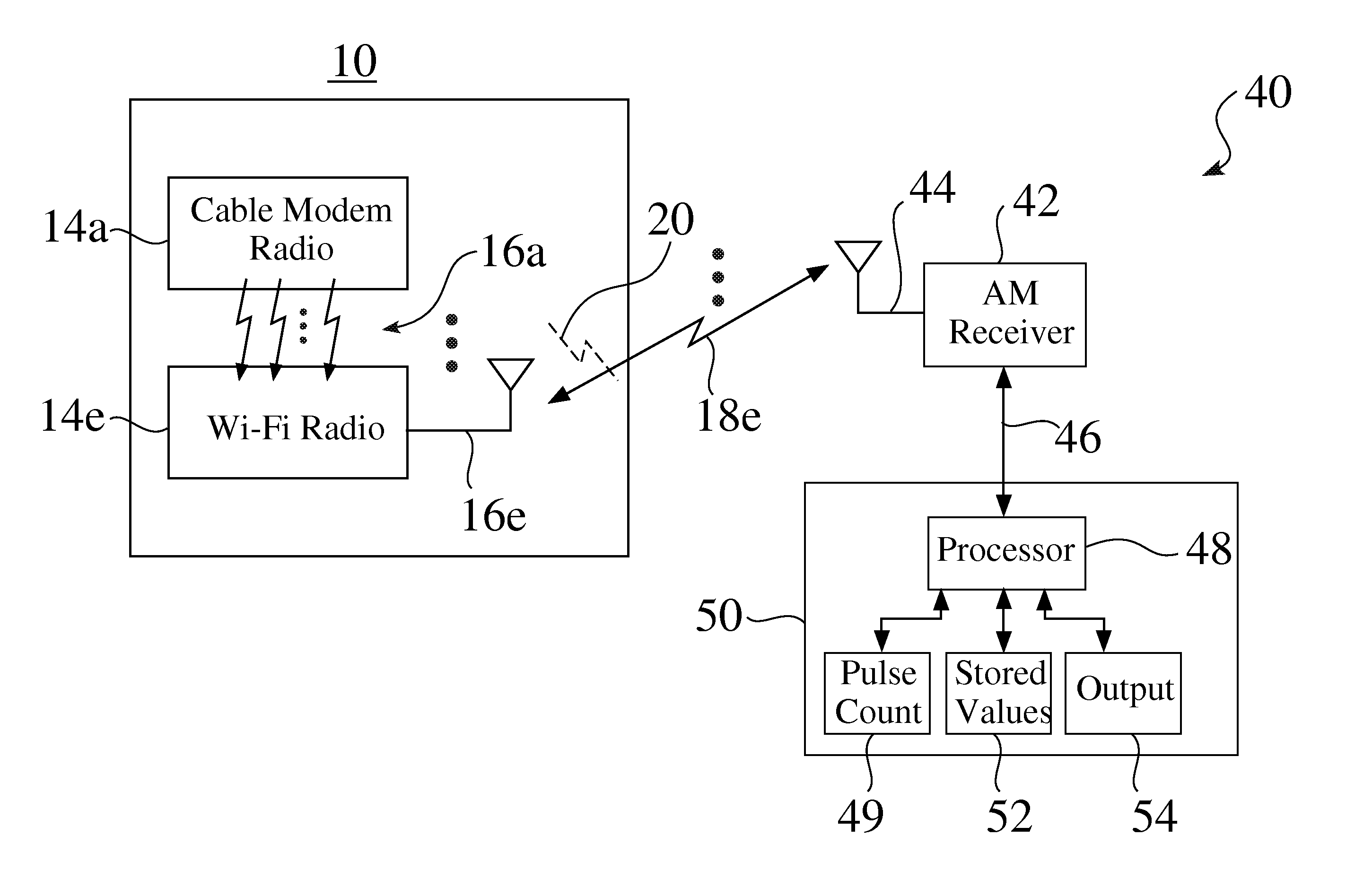
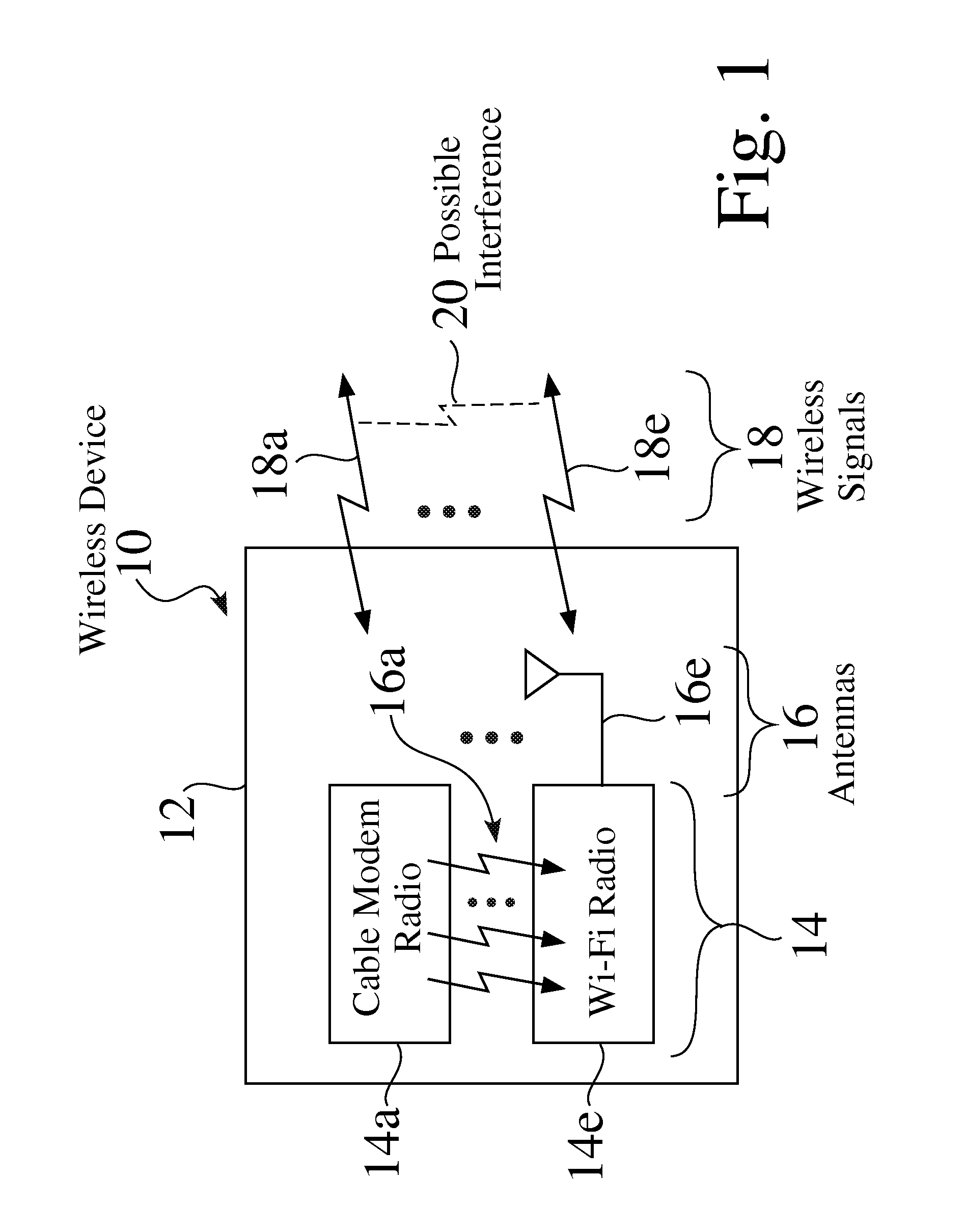
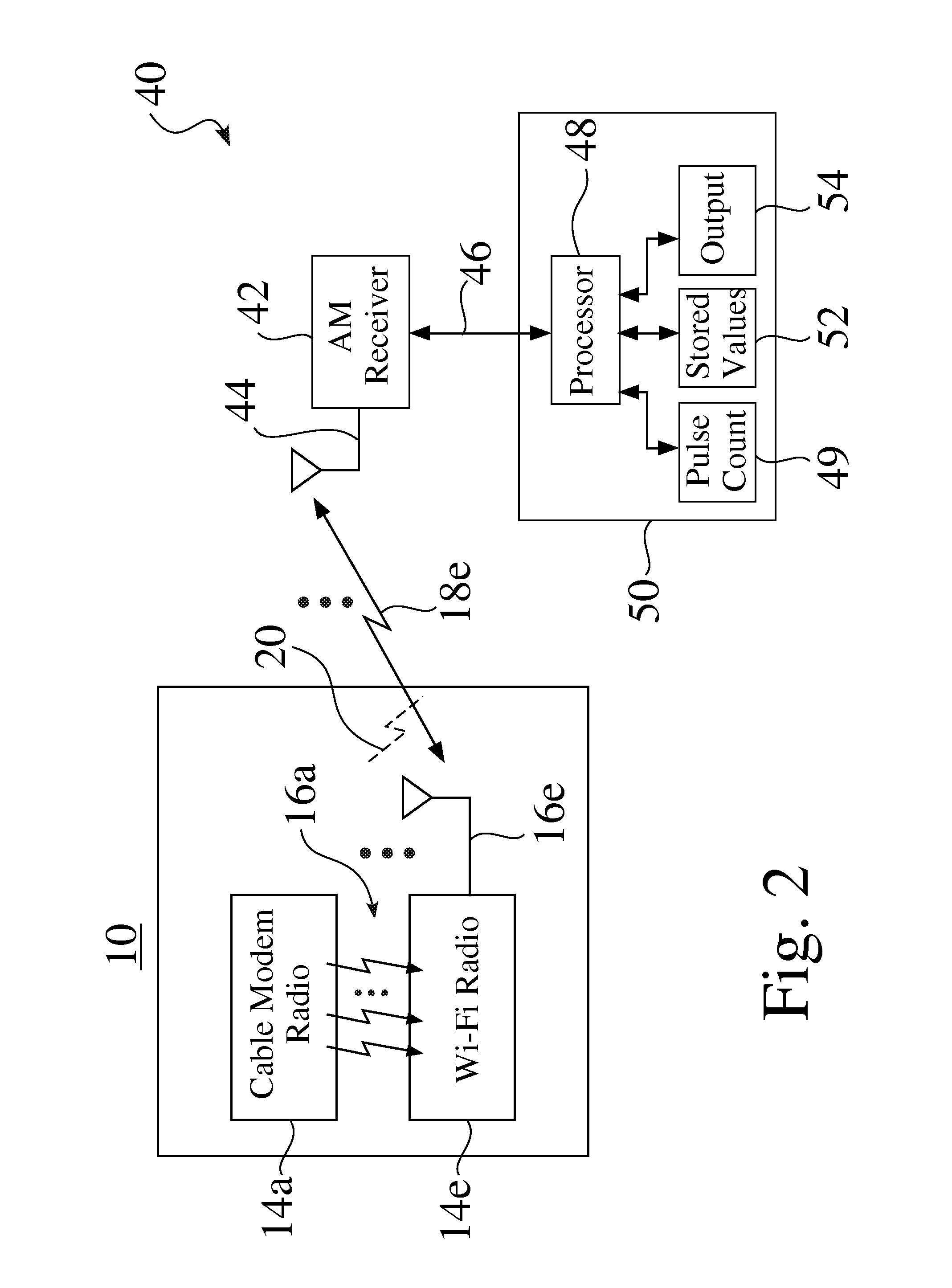
[0019]FIG. 1 is a partial schematic view of an exemplary wireless device 10, e.g. such as but not limited to a cable gateway or wireless router 10. The exemplary device 10 seen in FIG. 1 comprises an enclosure 12, a plurality of radio modules 14, e.g. 14a-14e, and a corresponding plurality of antennas 16, e.g. 16a-16e, for sending and / or receiving corresponding wireless signals 18, e.g. 18a-18e.

[0020]The first exemplary radio module 14a seen in FIG. 1 comprises a cable modem module 14a, while the second exemplary radio module 14e seen in FIG. 1 comprises a Wi-Fi radio module 14e.

[0021]While the radio modules 14a and 14e are typically configured to operate with different frequencies, the sub-harmonic or harmonic frequencies of a first radio 14a, e.g. a cable modem radio 14a, may land upon the frequency band of a second radio 14e, e.g. within a 2.4 GHz or 5.0 GHz band of a Wi-Fi band, which may result in interference 20 between the two signals 18a,18e.

[0022]While tests of the perfo...


PUM


Abstract

A receiver is provided that receives signals from a device under test (DUT) for one or more modes of operation. For each mode, the system detects beacon transmission signals from the DUT, and counts the number of beacons for a period of time. If the count is not consistent with an expected count, e.g. a stored value, the system may preferably provide an output to indicate that there is a problem with the DUT. If the count is consistent with the expected count, the system may preferably perform further testing for other modes of operation. If the count output of the DUT is consistent with expected counts over each of the operation modes, the system may provide an indication that the DUT has passed the beacon tests.

Description

BACKGROUND OF THE INVENTION[0001]1. Technical Field[0002]The invention relates generally to testing structures and processes for wireless or RF (radio frequency) communications systems. More particularly, the invention relates to test structures and processes for the determination of interference between wireless signals.[0003]2. Description of the Background Art[0004]It is necessary to equip receivers, transmitters, and transceivers with antennas that efficiently radiate, i.e. transmit and / or receive desired signals to / from other elements of a network to provide wireless connectivity and communication between devices in a wireless network, such as in a wireless PAN (personal area network), a wireless LAN (local area network), a wireless WAN (wide area network), a cellular network, or virtually any other radio network or system.[0005]Cable gateways and wireless routers commonly comprise a plurality of radios, e.g. two radios, such as comprising a first, e.g. cable modem radio, and a...

Claims


Application Information

Patent Timeline
Patent Type & Authority Patents(United States)
IPC IPC(8): H04B3/46H04W24/08
CPCH04W24/08H04W24/06H04W88/06
Inventor EMMANUEL, JOSEPH AMALAN ARULHUMMEL, JONATHAN M.ZARDOSHTI, SHAHROKH M.
Owner NETGEAR INC
Features
  • R&D
  • Intellectual Property
  • Life Sciences
  • Materials
  • Tech Scout
  • Unparalleled Data Quality
  • Higher Quality Content
  • 60% Fewer Hallucinations
Learn More