Combustion device for a gas turbine configured to suppress thermo-acoustical pulsations

a combustion device and gas turbine technology, applied in the direction of machines/engines, mechanical equipment, lighting and heating apparatus, etc., can solve the problems of low emission combustion devices operating in gas turbines, high risk of unstable combustion, and limited operating regime, so as to achieve no emissions and increase the effect of damage frequency

Inactive Publication Date: 2015-03-31
ANSALDO ENERGIA IP UK LTD
View PDF28 Cites 22 Cited by
  • Summary
  • Abstract
  • Description
  • Claims
  • Application Information

AI Technical Summary

Benefits of technology

[0020]A further aspect of the invention includes a combustion device with a high damping efficiency and low NOx emissions.

Problems solved by technology

During operation of gas turbines, heavy thermo-acoustical pulsations may be generated; these pulsations are very detrimental for the gas turbine lifetime (they can cause mechanical and thermal damages) and may also limit the operating regime; thus thermo-acoustical pulsations must be suppressed.
In particular, gas turbines operating with lean premixed, low emission combustion devices exhibit a high risk of unstable combustion that may cause these thermo-acoustical pulsations.
Cooling is a major problem in this structure and is achieved by impingement cooling, by air that, passing through the perforated outer wall, impinges on the perforated inner wall, to then enter the combustion device via the perforated inner wall.
Nevertheless, these combustion devices have a number of drawbacks.
This reduces the damping efficiency and, since this air does not take part in the combustion, the flame temperature and consequently the NOx emissions are higher than what is theoretically possible.
This drawback is even greater in the combustion devices having the noise absorbing perforated plate between the inner and the outer wall, since air (that is supplied via holes in the outer wall) cannot directly reach and impinge on the inner wall.
In addition, poor cooling may cause the temperature inside of the space between the inner and outer wall to rise, leading to an increase of the speed of the sound and thus shifting the damping frequency to a frequency different from the design frequency.
Advantageously, a large bandwidth frequency may be damped.

Method used


Image

  • Combustion device for a gas turbine configured to suppress thermo-acoustical pulsations
  • Combustion device for a gas turbine configured to suppress thermo-acoustical pulsations
  • Combustion device for a gas turbine configured to suppress thermo-acoustical pulsations

Examples


Embodiment Construction

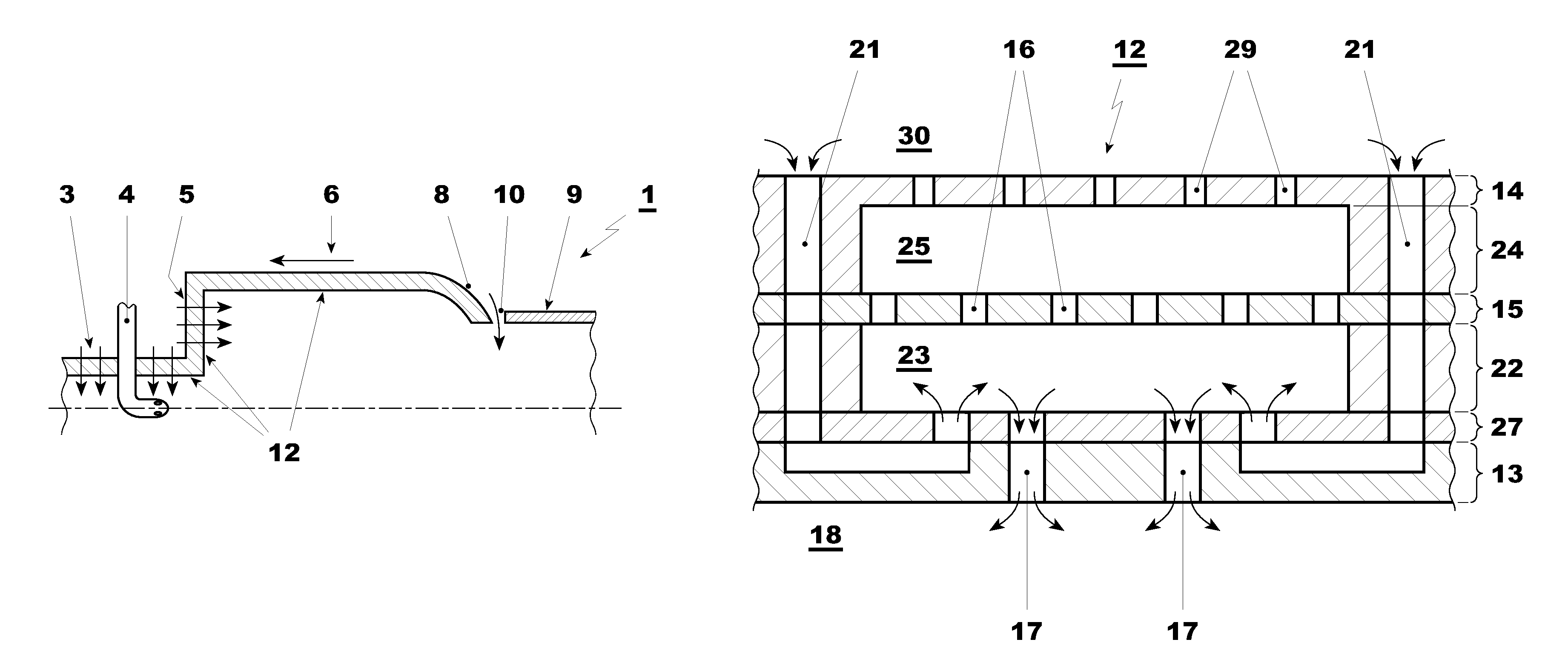
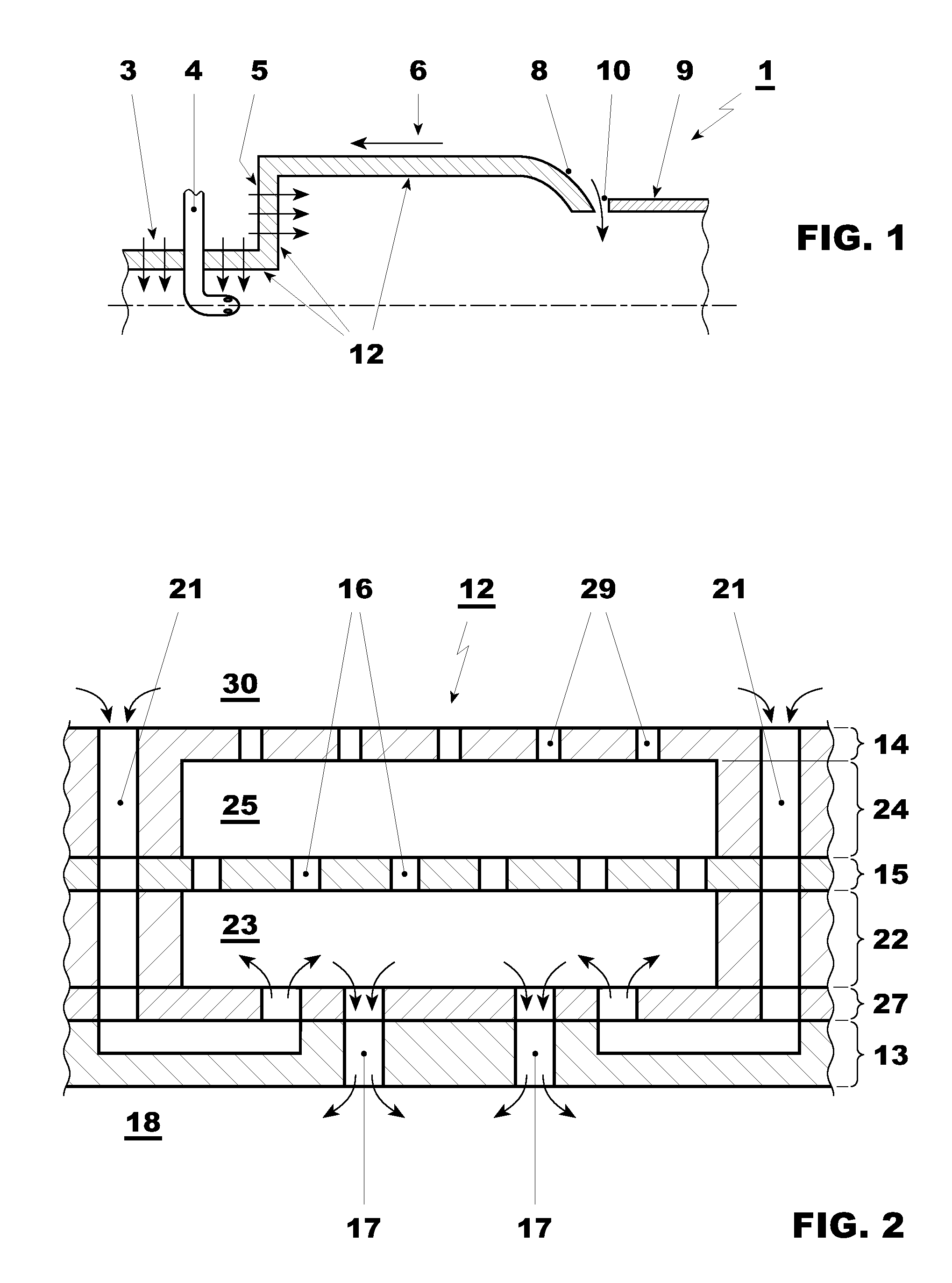
[0027]With reference to the figures, a combustion device for a gas turbine, generally indicated by the reference number 1, is illustrated.

[0028]The combustion device 1 is a first or a second combustion device of a sequential combustion gas turbine or also a combustion device of a traditional gas turbine having one single row of combustion devices; in the following, only reference to the second combustion device of a sequential combustion gas turbine is made and, in this respect, FIG. 1 shows such a second combustion device of a sequential combustion gas turbine having a mixing chamber 3 wherein an oxidizer, e.g., the flue gas still containing oxygen coming from a first combustion device, is introduced through an inlet (not shown).

[0029]The mixing chamber 3 is provided with a transversal lance 4 for injecting a fuel to be mixed with the oxidizer and combusted.

[0030]Downstream of the mixing chamber 3, the combustion device 1 has a front plate 5 and a combustion chamber 6 having a down...


PUM


Abstract

A combustion device (1) for a gas turbine includes portions (12) having an inner and an outer wall (13, 14) with an interposed noise absorption plate (15) having a plurality of holes (16). The combustion device (1) further has first passages (17) connecting zones between the inner wall (13) and the plate (15) to the inside of the combustion device (1) and second passages (21) for cooling the inner wall (13). The portions (12) also have an inner layer (22) between the inner wall (13) and the plate (15) defining inner chambers (23), each connected to at least a first passage (17), and an outer layer (24) between the outer wall (14) and the plate (15) defining outer chambers (25) connected to the inner chambers (23) via the holes (16) of the plate (15).

Description

[0001]This application claims priority to European App. No. 10 161 714.0, filed 3 May 2010, the entirety of which is incorporated by reference herein.BACKGROUND[0002]1. Field of Endeavor[0003]The present invention relates to a combustion device for a gas turbine. In particular the invention relates to a second combustion device of a sequential combustion gas turbine; sequential combustion gas turbines are known to have two rows of combustion devices, a second row being fed with the flue gases (still containing oxygen) coming from a first row of combustion devices.[0004]The present invention may also be implemented in different combustion devices, such as in combustion devices of the first combustion device row of a sequential combustion gas turbine or in a traditional gas turbine having one single row of combustion devices.[0005]For sake of clarity, simplicity and brevity in the following, specific reference to a combustion device of a second combustion device row of a gas turbine w...

Claims


Application Information

Patent Timeline
Patent Type & Authority Patents(United States)
IPC IPC(8): F02C7/24F23R3/00
CPCF23M20/005F23R3/002F23R2900/00014F23R2900/03041F23R2900/03043
Inventor HUBER, ANDREASNOIRAY, NICOLASSCHUERMANS, BRUNOBENZ, URS
Owner ANSALDO ENERGIA IP UK LTD
Why Eureka
Try Eureka