Imaging apparatus

a technology of imaging apparatus and viewfinder, which is applied in the field of imaging apparatus, can solve the problems of increasing man-hours and costs, preventing the observation of images, and adhering to the interior of the viewfinder,

Inactive Publication Date: 2015-03-31
CANON KK
View PDF10 Cites 0 Cited by
  • Summary
  • Abstract
  • Description
  • Claims
  • Application Information

AI Technical Summary

Benefits of technology

[0009]According to the present invention, it is possible to protect the display module arranged inside the viewfinder while adopting a structure not requiring complete sealing-up of the interior of the viewfinder of the imaging apparatus and allowing cleaning of the interior of the viewfinder by a blower.

Problems solved by technology

However, any foreign matter such as dust adhering to the interior of the viewfinder hinders the observation of the image.
However, in the construction discussed in Japanese Patent Application Laid-Open No. 5-68189, in which the dust-proof glass is arranged in an inclined state between the eyepiece lens and the eyepiece opening, it is necessary to provide space, resulting in an increase in the size of the viewfinder.
On the other hand, in the case where the dust-proof glass is arranged without being inclined, it is necessary for the surface of the dust-proof glass to be provided with coating for preventing reflection, resulting in an increase in man-hours and cost.
However, a display module arranged inside the viewfinder is very subject to fracture, and there is danger of the display module suffering damage by the blower during cleaning or the like.

Method used


Image

  • Imaging apparatus
  • Imaging apparatus
  • Imaging apparatus

Examples


Embodiment Construction

[0028]Various exemplary embodiments, features, and aspects of the invention will be described in detail below with reference to the drawings.

[0029]FIG. 16 is an external perspective view of a video camera constituting an example of an imaging apparatus to which the present invention is applied. As illustrated in FIG. 16, the video camera is equipped with a viewfinder 1.

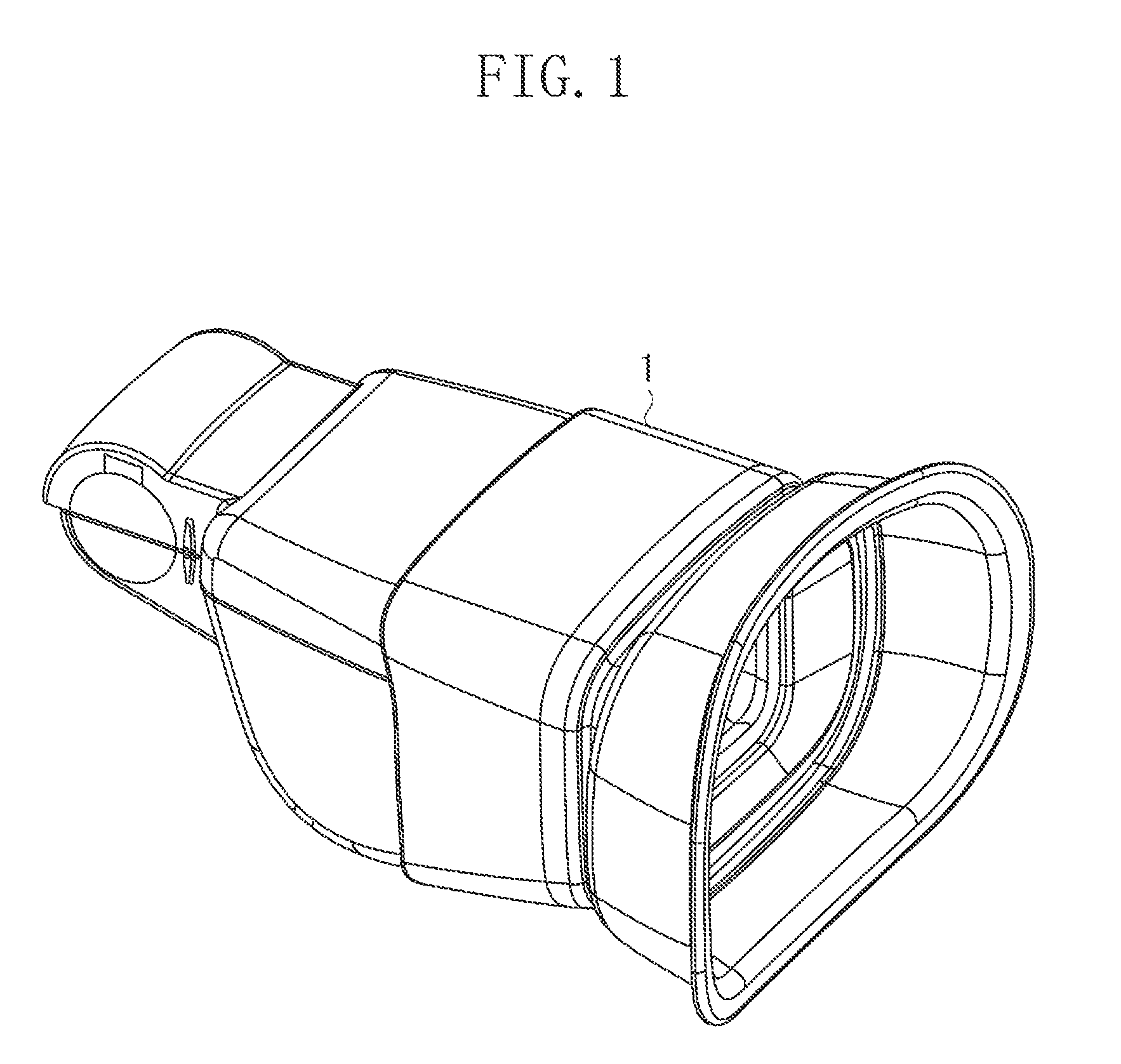
[0030]FIG. 1 is an external perspective view of the viewfinder 1. As illustrated in FIGS. 1 and 16, in the present exemplary embodiment, the upper, lower, right-hand, and left-hand sides of the viewfinder 1 as seen from the observer side will be defined as the upper, lower, right-hand, and left-hand sides of the imaging apparatus.

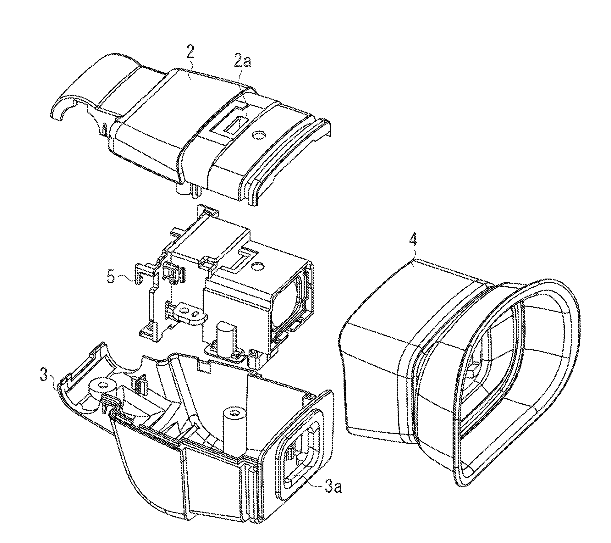
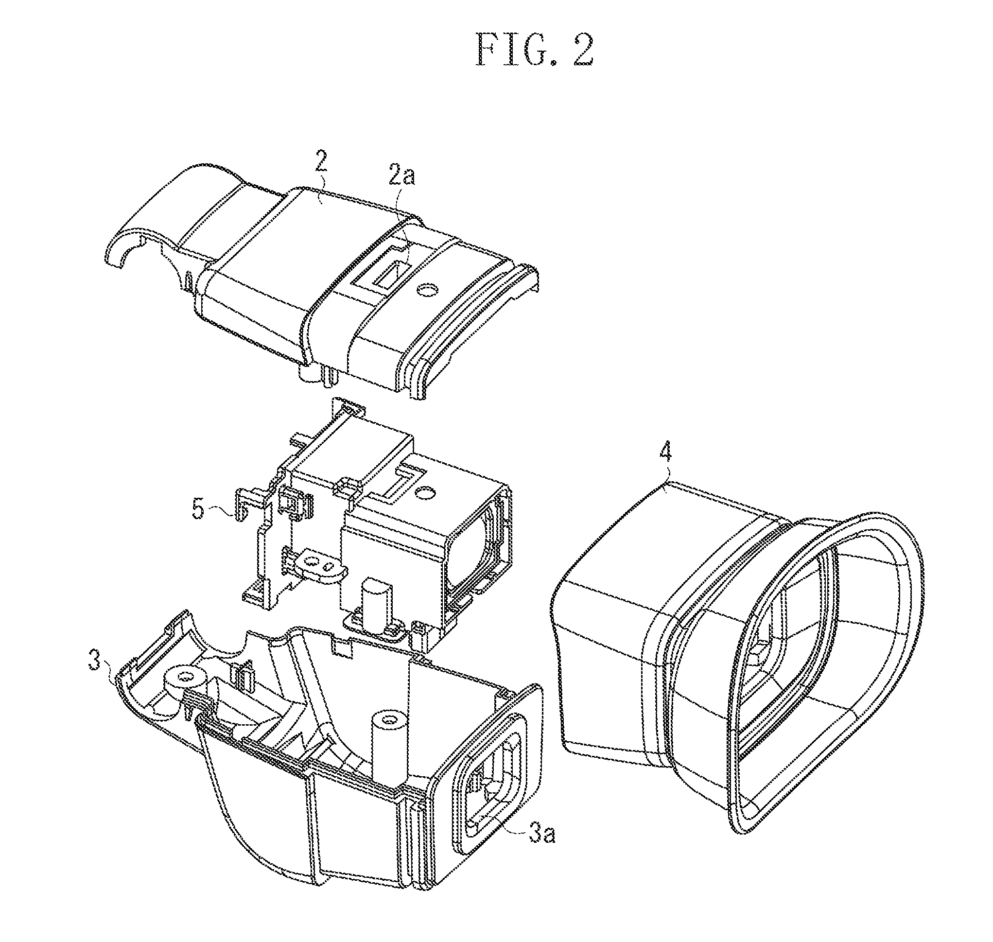
[0031]FIG. 2 is an exploded perspective view of the viewfinder 1.

[0032]The viewfinder 1 is constructed such that a viewfinder assembly 5 is covered with an upper cover 2, a lower cover 3, and an eyecup 4 that is attachable / detachable by the observer. An opening 2a is formed in the upper cover...


PUM


Abstract

An imaging apparatus includes: a display module; a dust-proof plate arranged on an observer side of the display module and configured to substantially seal a surface of the display module; an eyepiece lens arranged on the observer side of the dust-proof plate and movable in an optical axis direction; and a cover member retaining the dust-proof plate and the eyepiece lens, wherein the cover member has an opening for removing foreign matter adhering to the surface of the dust-proof plate opposed to the eyepiece lens and to the surface of the eyepiece lens opposed to the dust-proof plate.

Description

BACKGROUND OF THE INVENTION[0001]1. Field of the Invention[0002]The present invention relates to an imaging apparatus, and, in particular, to an imaging apparatus equipped with a viewfinder.[0003]2. Description of the Related Art[0004]Conventionally, the viewfinder of an imaging apparatus displays an image on a liquid crystal display unit based on a video signal during shooting. And, the image displayed on the liquid crystal display unit is enlarged at an eyepiece lens.[0005]However, any foreign matter such as dust adhering to the interior of the viewfinder hinders the observation of the image. In view of this, as is known in the art, a dust-proof glass is provided between the eyepiece lens and the eyepiece opening to seal up the interior of the viewfinder. Further, Japanese Patent Application Laid-Open No. 5-68189 discusses a construction in which the dust-proof glass is arranged in an inclined state so that the external light may not be reflected by the dust-proof glass.[0006]Howe...

Claims


Application Information

Patent Timeline
Patent Type & Authority Patents(United States)
IPC IPC(8): G02B23/16G02B25/00G02B27/00G03B13/06H04N5/225
CPCH04N5/2251G02B23/16G02B25/005G02B27/0006G03B13/06H04N23/52
Inventor UJIIE, HIROTAKA
Owner CANON KK
Why Eureka
Try Eureka