Plasma processing system, plasma measurement system, plasma measurement method, and plasma control system

a plasma control system and measurement system technology, applied in the field of plasma control system, plasma processing system, plasma measurement system, plasma measurement method, etc., can solve the problems of large change in the state of high-frequency electric power immediately below the substrate, difficult for the above measurement method to accurately control the plasma process, and large loss of high-frequency electric power during the transmission of high-frequency signals. , to achieve the effect of reducing the impedance of the power supply line, reducing the loss of high-frequency electric power

Inactive Publication Date: 2012-08-14
TOKYO ELECTRON LTD +1
View PDF7 Cites 0 Cited by
  • Summary
  • Abstract
  • Description
  • Claims
  • Application Information

AI Technical Summary

Benefits of technology

[0025]The load-impedance increase due to the capacitor may thus be cancelled using the resonance circuit connected in series to the capacitor. Reducing the impedance on the power-supply line to decrease the loss of the high-frequency electric power may additionally increase the amount of the high-frequency electric power available for the plasma control.
[0026]The plasma processing system may also include a stage in the processing chamber to support the target object, the power feeding portion may be provided in the stage, the capacitor may be provided partially or entirely in the power feeding portion at a position opposing the target object supported by the stage, and the capacitor may be formed in the stage. The capacitor may provide the particle source. The capacitor may thus be embedded in the stage to keep the interior of the processing chamber clean.
[0034]The matching box is thus provided between the high-frequency power supply and the power-feeding portion. Upstream of the matching box, the feedback control may optimize the high-frequency electric power from the high-frequency power supply, while downstream of the matching box, the matching box may match the load impedance that changes constantly with the output impedance of the high-frequency power supply. The loss of the high-frequency electric power from the high-frequency power supply may thus be minimized, thereby maximizing the use of the high-frequency electric power for the plasma control.

Problems solved by technology

In this way, the loss of the high-frequency electric power during the transmission of the high-frequency signal is relatively large and changes over time depending on the condition of the processing chamber.
From these reasons, in the above measurement method that measures the voltage and the power at the measurement position P apart from the substrate, it is difficult to accurately understand the state of the high-frequency electric power immediately below the substrate.
It may be difficult for the above measurement method to control the plasma process accurately or to perform the plasma process more stably.
This procedure is rather complicated.
Such a large loss or variation of the high-frequency electric power during the transmission of the high-frequency signal may unexpectedly change the process speed.

Method used


Image

  • Plasma processing system, plasma measurement system, plasma measurement method, and plasma control system
  • Plasma processing system, plasma measurement system, plasma measurement method, and plasma control system
  • Plasma processing system, plasma measurement system, plasma measurement method, and plasma control system

Examples


first modification

(First Modification)

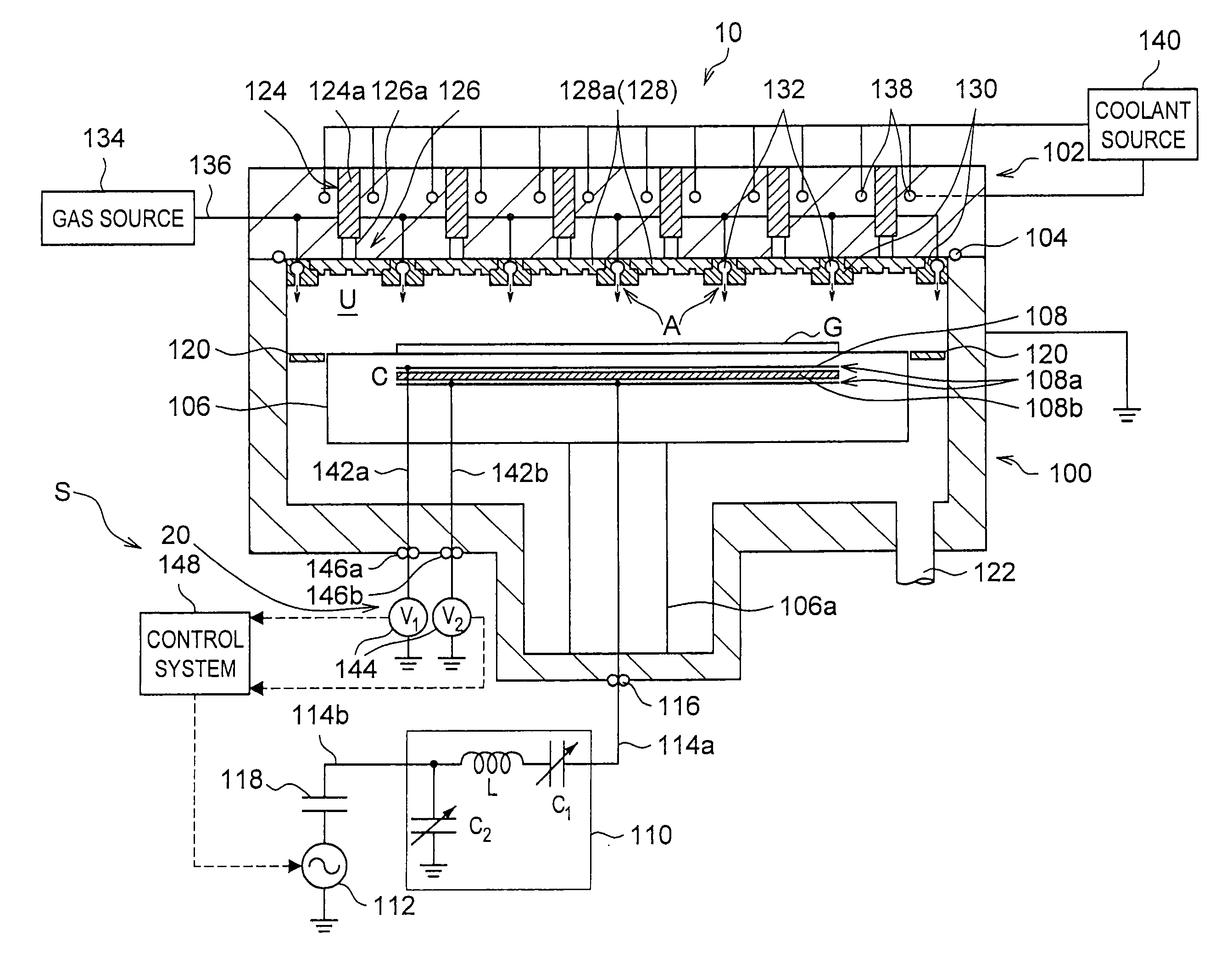
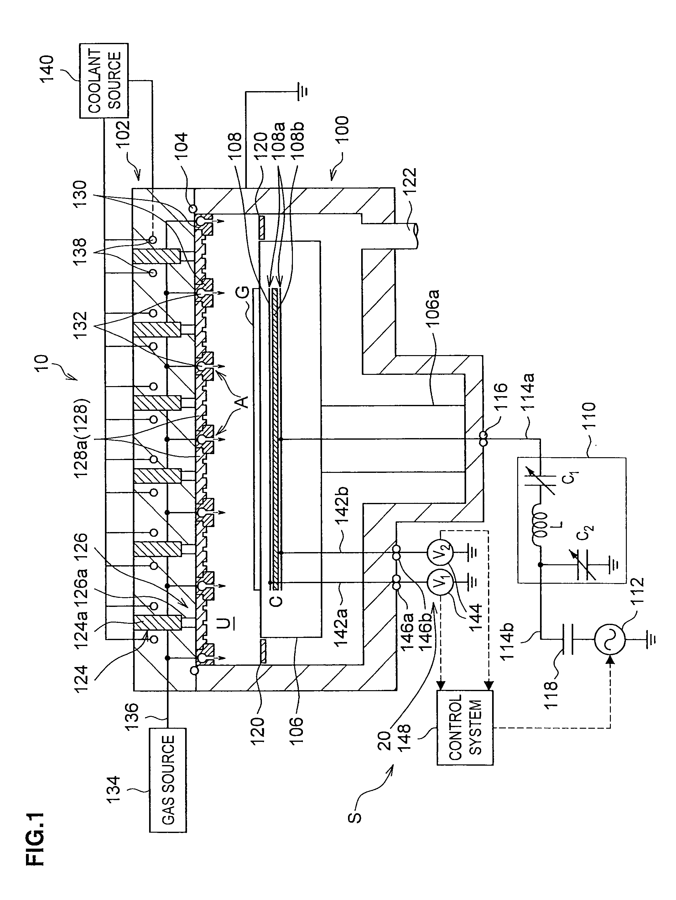
[0131]The second way proposed by the applicants to set the capacitance C of the capacitor 108a to 4.2 times or less than the sheath capacitance Csheath is as follows. With reference to FIG. 9, small electrodes (capacitor 108a) are formed at the end of the susceptor 106. This position is not opposed to the substrate G. i.e., has little effect on the plasma process.

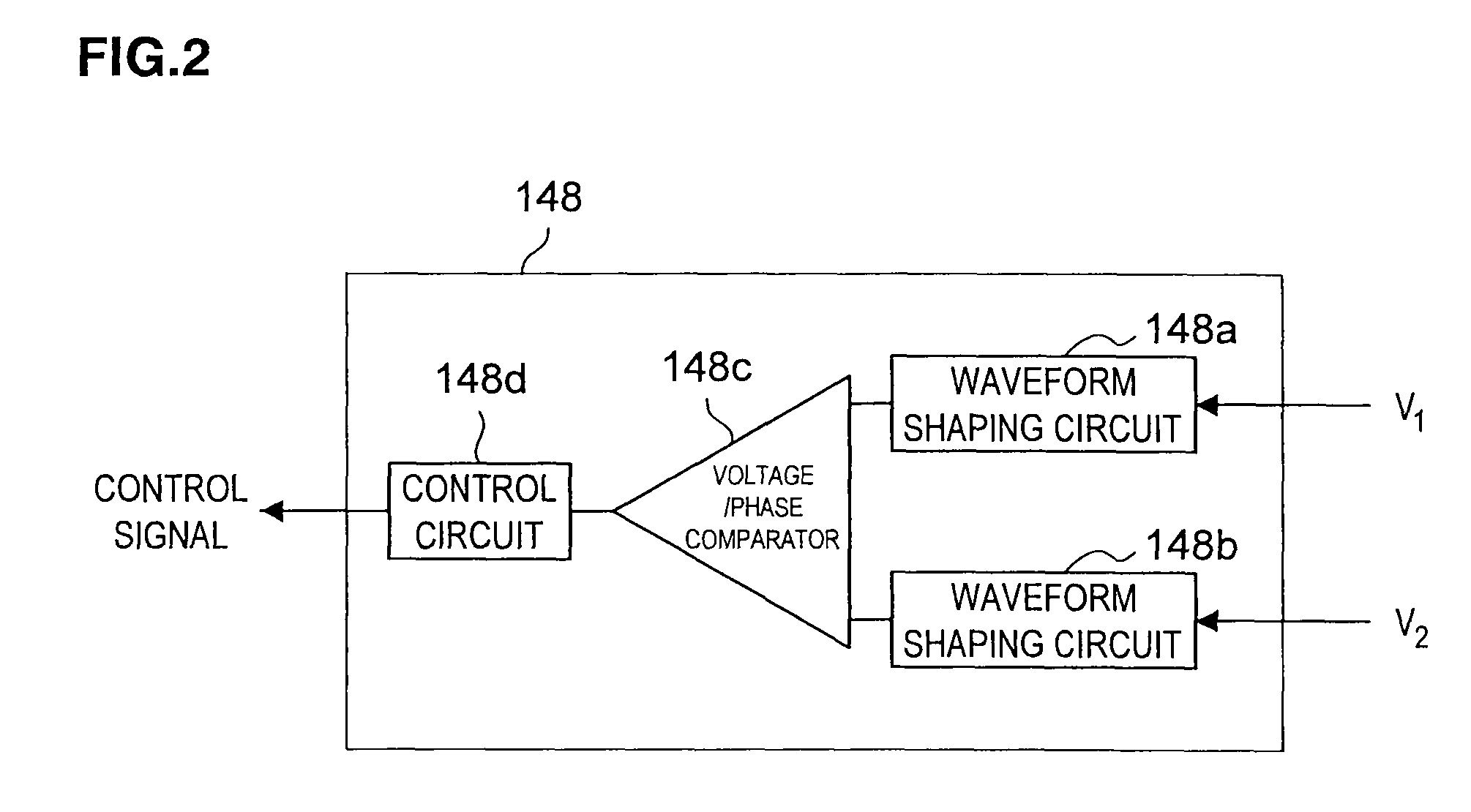
[0132]In this method, like the first method, the voltages V1 and V2 at the pair of plates of the capacitor may be actually measured and the high-frequency electric power P of the susceptor 106 may be computed from the actual measurements, thereby deriving the high-frequency electric power immediately below the substrate, the electric power being available for the plasma control. Additionally, the method in the first modification may measure the voltages V1 and V2 with little effect on the plasma process. The capacitance of the capacitor 108a may easily be reduced. Note, however, that the voltages V1 and ...

second modification

(Second Modification)

[0133]The third way proposed by the applicants to set the capacitance C of the capacitor 108a to 4.2 times or less than the sheath capacitance Csheath is as follows. With reference to FIG. 10, the capacitor 108a is provided in the power feeding rod 106a below the susceptor 106, the capacitor 108a being connected to the power-supply line 114a.

[0134]Also in this method, the voltages V1 and V2 at the pair of plates of the capacitor 108a may be actually measured and the high-frequency electric power P of the susceptor 106 may be computed from the actual measurements, thereby deriving the high-frequency electric power immediately below the substrate, the electric power being available for the plasma control. Note, however, that a power leak from the bottom of the susceptor 106 to the processing chamber 100 may not be detected.

third modification

(Third Modification)

[0135]With reference to FIG. 11, for example, for any of the capacitors 108a shown in FIG. 1, FIG. 9, and FIG. 10, an inductor 150 as a resonance circuit (LC=1 / ω02; ω0 is a resonance frequency) may be connected in series with the capacitor 108a.

[0136]The load-impedance increase due to the capacitor 108a may thus be cancelled by the inductor 150 (serial resonance circuit), thereby reducing the impedance of the power-supply line 114a. The load of the matching box 110 may thus also be reduced.

[0137]According to the above embodiments and the modifications thereof, the capacitor 108a may be used to accurately measure the power immediately below the substrate.

[0138]Although in the above embodiments, the voltages of the electrical signals at the pair of plates of the capacitor 108a are measured as the parameters to control the plasma, the present invention is not limited thereto. At least one of the voltage, the current, and the phase at the pair of plates of the capac...


PUM

PropertyMeasurementUnit
capacitanceaaaaaaaaaa
capacitance C32aaaaaaaaaa
pressureaaaaaaaaaa

Abstract

A microwave plasma processing system 10 includes: a processing chamber 100 in which a desired process is applied to a target object using a plasma; a susceptor 106 (stage) in the processing chamber 100 to support the target object; a high-frequency power supply 112 supplying high-frequency electric power to the susceptor 106; a capacitor 108a provided to the susceptor 106; and a measurement device 20 measuring voltages at the pair of plates of the capacitor 108a when high-frequency electric power is supplied from the high-frequency power supply 112 to the susceptor 106.

Description

CROSS-REFERENCE TO RELATED APPLICATION[0001]The present invention contains subject matter related to Japanese Patent Application JP2007-094965, filed in the Japan Patent Office on Mar. 30, 2007, and Japanese Patent Application JP2008-079584, filed in the Japan Patent Office on Mar. 26, 2008, and the entire contents of which being incorporated herein by reference.BACKGROUND OF THE INVENTION[0002]1. Field of the Invention[0003]The present invention relates to a plasma processing system that is able to measure a parameter for plasma control, a system and a method for measuring a parameter for plasma control, and a system for controlling a plasma processing system that is able to measure a parameter for plasma control.[0004]2. Description of the Related Art[0005]FIG. 15 shows a generally known plasma processing system 1000. The system 1000 includes a processing chamber U in which gases are ionized into a plasma. The plasma is used to apply a substrate G with a plasma process such as an ...

Claims


Application Information

Patent Timeline
Patent Type & Authority Patents(United States)
IPC IPC(8): H01L21/00C23C16/00C23C14/00
CPCH01J37/32192H01J37/32935H01J37/3299
Inventor KATO, MITSUOSUGIYAMA, MASAKIHIROE, AKIHIKOOHMI, TADAHIROHIRAYAMA, MASAKI
Owner TOKYO ELECTRON LTD
Why Eureka
Try Eureka