Fluorescence and delayed fluorescence-type organic light-emitting material and element

a fluorescence-type organic light-emitting material and fluorescence-type technology, applied in the field of fluorescence-type fluorescence-type organic light-emitting materials and elements, can solve the problems of not obtaining high quantum yield in many cases in general, providing significantly lower luminous efficiency than a theoretical value, and none of the literatures disclose the relationship between luminous efficiency and luminous efficiency. achieve high efficiency and practical value

Active Publication Date: 2015-03-31
KYUSHU UNIV +1
View PDF25 Cites 138 Cited by
  • Summary
  • Abstract
  • Description
  • Claims
  • Application Information

AI Technical Summary

Benefits of technology

[0013]An object of the present invention is to provide a highly efficient and practically useful organic light-emitting element and an organic light-emitting material suitable for the organic light-emitting element.

Problems solved by technology

However, a conventional fluorescent organic compound involves the following fundamental problem in terms of excitation efficiency of the compound.
However, in the phosphorescence, the excited triplet state has a long lifetime, and hence deactivation of energy occurs through saturation of an excited state and interactions with excitons in an excited triplet state, with the result that a high quantum yield is not obtained in many cases in general.
However, none of the literatures discloses a relationship between the luminous efficiency and a difference between excited singlet energy and excited triplet energy and has any description suggesting the possibility of delayed fluorescence in an organic compound containing no metal atom other than the porphyrin-based metal complex.
Further, the organic EL element according to each of the reports provides significantly lower luminous efficiency than a theoretical value.
However, none of the literatures discloses that delayed fluorescence is emitted in light emission of the compound itself.

Method used


Image

  • Fluorescence and delayed fluorescence-type organic light-emitting material and element
  • Fluorescence and delayed fluorescence-type organic light-emitting material and element
  • Fluorescence and delayed fluorescence-type organic light-emitting material and element

Examples


synthetic example 1

Synthesis of Compound (11)

[0096]33.3 g (297.0 mmol) of 1,2-cyclohexanedione and 86.0 g (594.7 mmol) of phenylhydrazine hydrochloride were loaded into a 2,000-ml three-necked flask subjected to degassing and nitrogen purging, 1,000 ml of ethanol were added thereto, and the mixture was stirred. After that, 3.0 g (30.6 mmol) of concentrated sulfuric acid were added dropwise to the flask over 5 minutes and the mixture was then heated to 65° C. and stirred for 4 hours. The resultant mixture was cooled to room temperature and the precipitated purple-brown crystal was then collected by filtration. The crystal collected by filtration was washed by reslurrying twice with 500 ml of ethanol. The resultant was dried under reduced pressure to afford 80.0 g (280.5 mmol, 96.3% yield) of a purple-brown powder.

[0097]Next, 72.0 g (261.5 mmol) of the purple-brown powder described above were loaded into a 1,000-ml three-necked flask, 720 g of acetic acid and 72.0 g of trifluoroacetic acid were added th...

example 1

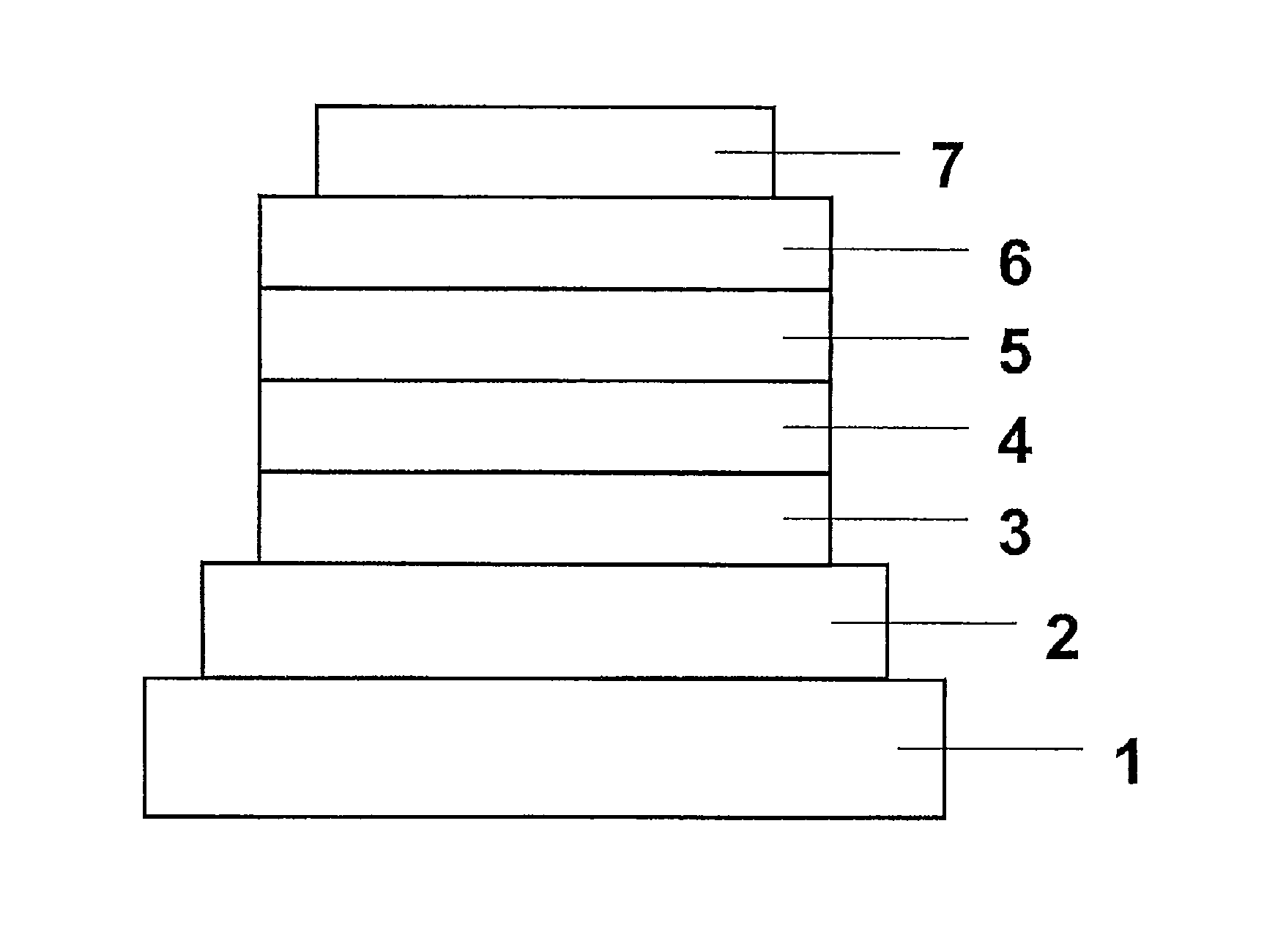
[0102]On a glass substrate, Compound (11) was deposited from the vapor from a vapor deposition source under the condition of a degree of vacuum of 5.0×10⁻⁴ Pa by a vacuum vapor deposition method so as to form a thin film having a thickness of 100 nm at a rate of 0.2 nm / sec. The produced thin film was irradiated with light having a wavelength of 337 nm with N2 laser. An emission spectrum from the thin film upon the irradiation was evaluated at a temperature of 5 K. As a result, fluorescence emission at 466 nm and phosphoresce emission at 486 nm were confirmed. Based on the wavelengths, the excited singlet energy and excited triplet energy of Compound (11) were found to be 2.66 eV and 2.55 eV, respectively. Further, a difference between the excited singlet energy and the excited triplet energy (ΔE) was 0.11 eV.

example 2 (

Example 2(R)

[0103]On a glass substrate, 1,3-dicarbazolylbenzene (mCP) was deposited from a vapor deposition source under the condition of a degree of vacuum of 5.0×10⁻⁴ Pa by a vacuum vapor deposition method so as to form a thin film having a thickness of 100 nm at a rate of 0.2 nm / sec. The produced thin film was irradiated with light having a wavelength of 337 nm with N2 laser. An emission spectrum from the thin film upon the irradiation was evaluated at a temperature of 5 K. As a result, fluorescence emission at 375 nm and phosphoresce emission at 420 nm were confirmed. Based on the wavelengths, the excited singlet energy and excited triplet energy of mCP were found to be 3.30 eV and 2.95 eV, respectively.

[0104]mCP is calculated to have excited singlet energy and excited triplet energy higher by 0.64 eV and higher by 0.4 eV, respectively, than the excited singlet energy and excited triplet energy of Compound (11).


PUM

PropertyMeasurementUnit
excited triplet energyaaaaaaaaaa

Abstract

Fluorescence-emitting material which improves luminous efficiency of an organic light-emitting element such as an organic EL element or an organic PL element and an organic light-emitting element using the fluorescence-emitting material. The fluorescence-emitting material includes a compound having an indolocarbazole skeleton represented by the following general formula (1), as defined in the specification.The organic light-emitting element includes an organic EL element including: a substrate; an anode; a cathode; and a light-emitting layer, the anode and the cathode being laminated on the substrate and the light-emitting layer being sandwiched between the anode and the cathode, in which the light-emitting layer includes: the organic light-emitting material; and as a host material, an organic compound having excited triplet energy higher than that of the organic light-emitting material.

Description

TECHNICAL FIELD[0001]The present invention relates to a novel organic light-emitting material which emits fluorescence and delayed fluorescence and an organic light-emitting element using the organic light-emitting material.BACKGROUND ART[0002]In general, an organic light-emitting element has such a configuration that a thin film including an organic light-emitting material is formed on a substrate as its simplest structure. The organic light-emitting element is subjected to optical and electrical excitation so as to emit light. As a result, light is emitted from the organic light-emitting element. A photo luminescence element (PL element), in which optical excitation is performed, serves as the organic light-emitting element as long as at least the above-mentioned element configuration is satisfied. That is, the PL element utilizes a phenomenon in which an organic light-emitting material is excited by being irradiated with light depending on a light absorption wavelength of the org...

Claims


Application Information

Patent Timeline
Patent Type & Authority Patents(United States)
IPC IPC(8): H01L51/54C09K11/06H05B33/10C09B57/00H01L51/00H01L51/50
CPCH05B33/10C09B57/00C09K11/06H01L51/0072H01L51/5012C09K2211/1007C09K2211/1011C09K2211/1029C09K2211/1044C09K2211/1059Y10S428/917C07D209/86C07D487/04H10K85/6572H10K50/11H10K2101/20C09K2211/1018
Inventor ENDO, AYATAKAADACHI, CHIHAYAYOSHIMURA, KAZUAKIKAWADA, ATSUSHIMIYAZAKI, HIROSHIKAI, TAKAHIRO
Owner KYUSHU UNIV
Why Eureka
Try Eureka