
Rear suspension mounting structure for electric vehicle

a rear suspension and electric vehicle technology, applied in the direction of electric propulsion mounting, propulsion parts, transportation and packaging, etc., can solve the problems of reducing the overall weight of the vehicle, reducing the efficiency of package utilization, and lowering the energy loss during power transmission, so as to enhance steering stability and reduce overall weight

Active Publication Date: 2015-04-07
HYUNDAI WIA
View PDF25 Cites 6 Cited by
  • Summary
  • Abstract
  • Description
  • Claims
  • Application Information

AI Technical Summary

Benefits of technology

The structure achieves reduced weight, enhanced steering stability, improved cooling of the driving motor, and increased packaging efficiency, along with protection during rear-end collisions, by utilizing dissimilar metals for the torsion beam and trailing arm.

Problems solved by technology

Therefore, when the in-wheel motor is employed, a power transmission device, such as differential gears, may not be provided, thereby reducing the vehicle weight and lowering an energy loss during power transmission.
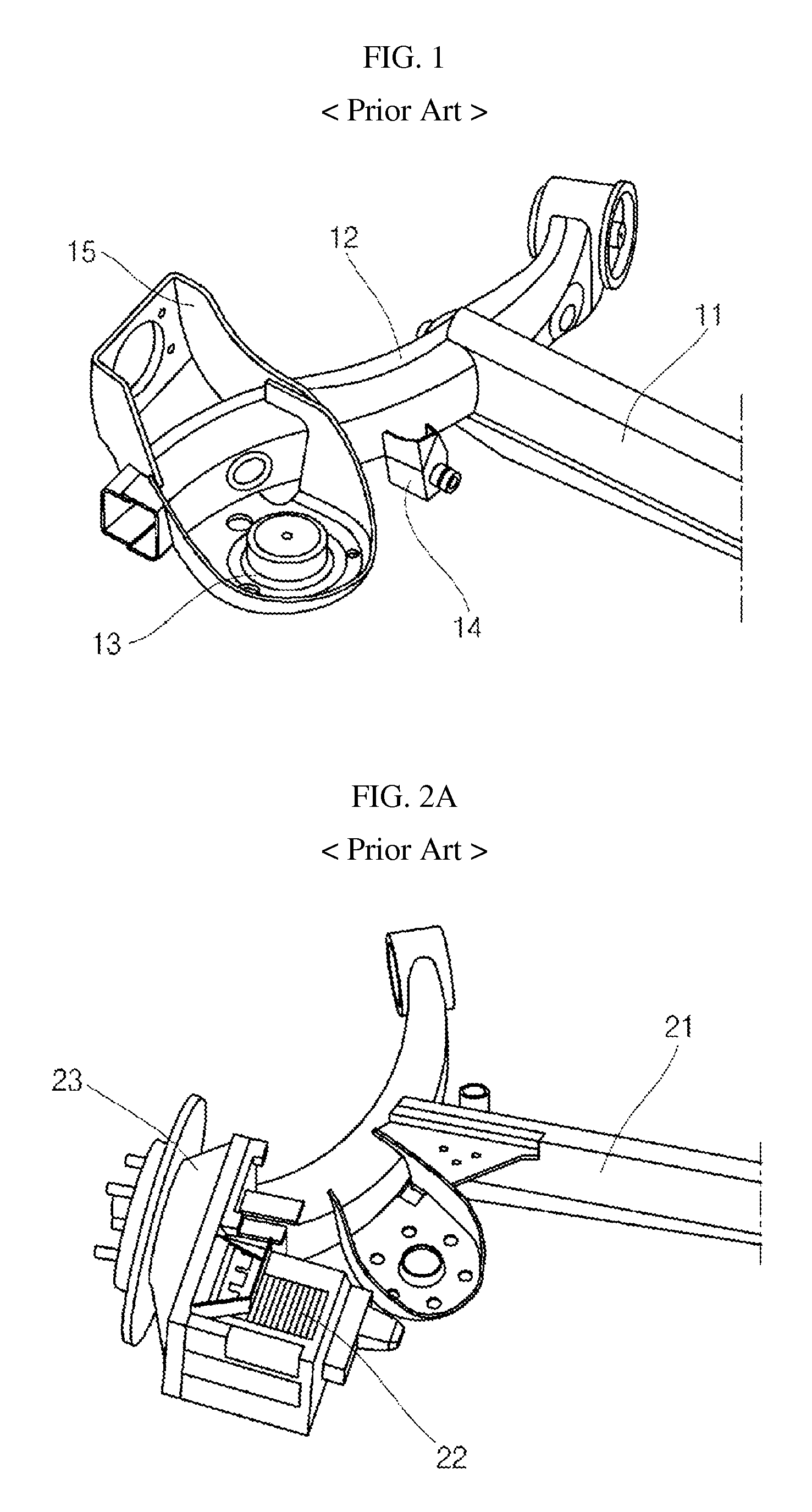
However, in the conventional rear suspension mounting structure for an electric vehicle, in order to add a driving motor to a coupled torsion beam axle, a separate fastening structure and additional space are required, which is disadvantageous in view of package utilization efficiency.
In addition, the separate fastening structure and additional space increase an unsprung mass, which is disadvantageous in view of riding comfort and steering stability.
In this case, however, it is difficult to achieve durability.

Method used


Image

  • Rear suspension mounting structure for electric vehicle
  • Rear suspension mounting structure for electric vehicle
  • Rear suspension mounting structure for electric vehicle

Examples


Embodiment Construction

[0044]The present invention now will be described more fully hereinafter with reference to the accompanying drawings, in which embodiments of the invention are shown. This invention may, however, be embodied in many different forms and should not be construed as limited to the embodiments set forth herein. Rather, these embodiments are provided so that this disclosure will be thorough and complete, and will fully convey the scope of the invention to those skilled in the art.

[0045]The terminology used herein is for the purpose of describing particular embodiments only and is not intended to be limiting of the invention. As used herein, the singular forms “a”, “an” and “the” are intended to include the plural forms as well, unless the context clearly indicates otherwise. It will be further understood that the terms “comprises” and / or “comprising,” when used in this specification, specify the presence of stated features, integers, steps, operations, elements, and / or components, but do ...


PUM


Abstract

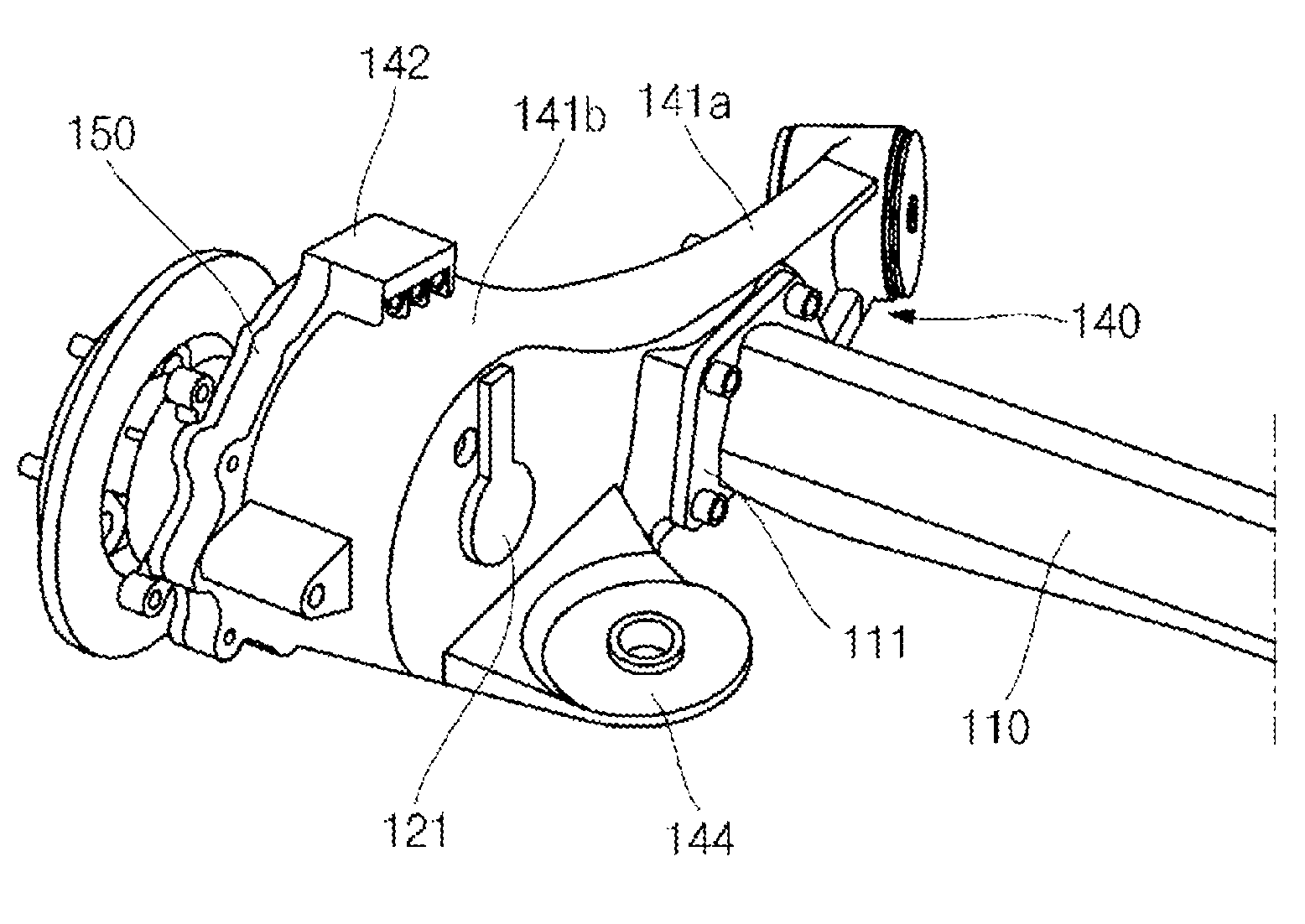
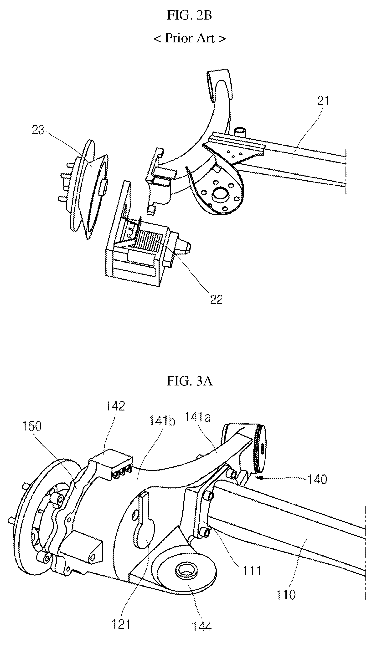
Provided is a rear suspension mounting structure for an electric vehicle, which can reduce the overall weight and can enhance steering stability by forming a torsion beam and a trailing arm using different materials. In one embodiment, the rear suspension mounting structure includes a hub fastened to the center of a wheel, a trailing arm including a housing producing an internal space and an arm bush extending to one side of the housing, a torsion beam bolt-coupled to the arm bush through a coupling plate, a motor coupled to the internal space of the housing and supplying a driving force, a motor cover provided in the internal space of the housing, and a driving speed reducer provided at the outside of the motor cover in the internal space of the housing, wherein the torsion beam and the trailing arm are formed using dissimilar metals.

Description

CROSS-REFERENCE TO RELATED APPLICATION[0001]This application claims priority to and the benefit of Korean Patent Application No. 10-2013-0071801 filed on Jun. 21, 2013, which is herein incorporated by reference in its entirety.BACKGROUND OF THE INVENTION[0002]1. Field of the Invention[0003]Aspects of the present invention relate to a rear suspension mounting structure for an electric vehicle.[0004]2. Description of the Related Art[0005]In general, a suspension system for vehicles absorbs vibration and impact transmitted from the wheels to the vehicle body during a movement of a vehicle, thus preventing damage to the vehicle body and freight caused by the vibration and impact, in addition to allowing passengers to feel comfortable. The suspension system includes a front suspension and a rear suspension.[0006]In particular, in a four wheel drive (4WD) in-wheel electric vehicle, a rear suspension system is configured to directly transmit power to a wheel by a motor disposed within the ...

Claims


Application Information

Patent Timeline
Patent Type & Authority Patents(United States)
IPC IPC(8): B60G3/12B60G21/05B60K1/00B60G7/00
CPCB60G7/001B60G21/051B60G2200/23B60G2204/182B60G2206/201B60G2206/8207B60G2300/50B60G7/02B60G11/18B62D21/00
Inventor LEE, EUN CHANG
Owner HYUNDAI WIA
Learn More