Construction machine

a construction machine and construction technology, applied in the direction of friction roller based transmission, steering device, cycle equipment, etc., can solve the problems of increasing manufacturing cost, fuel tank displacement, and increasing number of components, so as to reduce manufacturing cost, increase fuel tank capacity, and maintain low cost

Active Publication Date: 2015-04-07
NIHON KENKI CO LTD
View PDF10 Cites 2 Cited by
  • Summary
  • Abstract
  • Description
  • Claims
  • Application Information

AI Technical Summary

Benefits of technology

[0015]In view of the above-described problems of the conventional art, it is an object of the present invention to provide a construction machine which can firmly fix the fuel tank without incurring an increase in the number of components.
[0018]With this arrangement, since the fuel tank is reliably fixed by the vertical restraining element and the lateral restraining element in the two directions (or more specifically, in the three axial directions), that is, in the horizontal direction (front-rear direction and left-right direction) and the perpendicular direction (vertical direction), dislocation of the fuel tank with respect to the revolving frame caused by vibration during traveling or working of the construction machine can be suppressed. As a result, dislocation of the fuel tank and contact with the peripheral mounted devices can be prevented. Therefore, a clearance between the fuel tank and the peripheral mounted equipment can be set smaller, and a capacity of the fuel tank can be sufficiently ensured by that portion.
[0019]Moreover, since the vertical restraining element and the lateral restraining element can be mounted by using the mounting member across a part of the swing cylinder and the operating oil tank, it is not necessary to individually mount the vertical restraining element and the lateral restraining element by using the respective dedicated fixture or the like. As a result, an increase in the number of components can be suppressed, and contribution can be also made to reduce a manufacturing cost. In addition, by detachably attaching the vertical restraining element and the lateral restraining element to the mounting member or the operating oil tank, the fuel tank can be easily made detachable when the fuel tank is to be replaced or during a maintenance work of the swing cylinder and the like.
[0023](4) According to the present invention, the connecting member mounted on the operating oil tank is configured to be provided either at an upper-part position on the front surface or at a front-part position on the upper surface of the operating oil tank. With this arrangement, by mounting the connecting member on the operating oil tank, the connecting member can be brought into contact with the upper surface of the fuel tank, and movement of the fuel tank in the vertical direction can be regulated.
[0025]With this arrangement, since the shallow bottom portion of the fuel tank is arranged on the upper side of the swing cylinder through the mounting member, the capacity of the fuel tank can be increased by using an upper space of the swing cylinder. Moreover, since the lower end side of the vertical restraining element and the front end side of the lateral restraining element are fixed to the same mounting member, the number of components can be reduced, and a manufacturing cost can be kept low.
[0026](6) According to the present invention, the upper revolving structure is formed as a rear small-revolving type defining a distance between a revolving center with respect to the lower traveling structure and the counterweight as a revolving radius; and the fuel tank is formed having an arc shape so that the side surface portion on the outside is contained in the revolving radius. With this arrangement, when the upper revolving structure makes a revolving operation, the side surface on the outside of the fuel tank does not protrude from the revolving radius of the upper revolving structure, and safety of the revolving operation can be improved.

Problems solved by technology

Thus, the fuel tank can be restrained only in either one of a horizontal direction or a perpendicular direction (vertical direction), and it has a problem that the fuel tank might be displaced by vibration of the hydraulic excavator.
However, with this conventional art, a dedicated mounting base is required for fixing the fuel tank, and it has a problem that the number of components increases and a manufacturing cost rises.

Method used


Image

  • Construction machine
  • Construction machine
  • Construction machine

Examples


Embodiment Construction

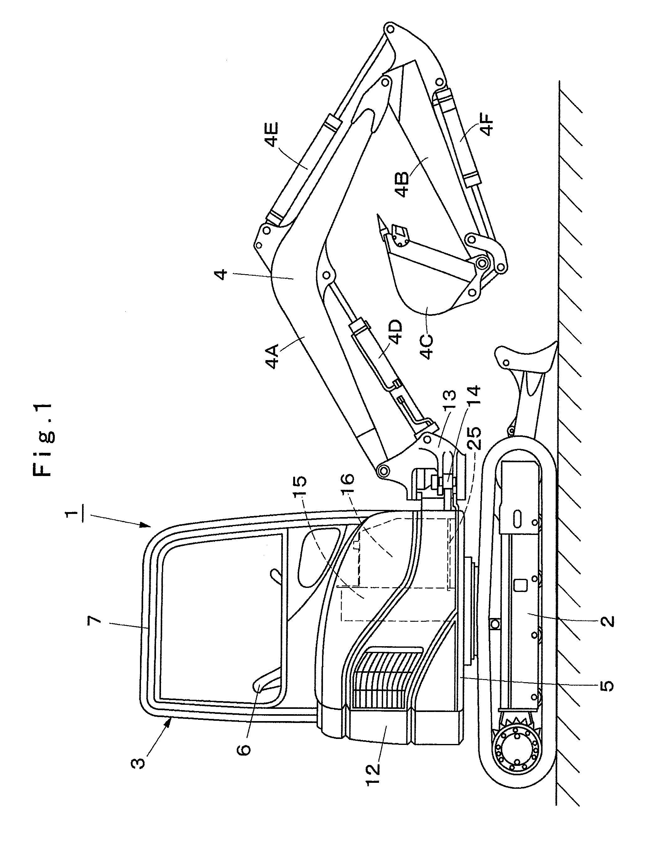
[0036]An embodiment of a construction machine according to the present invention will be described below in detail by referring to FIGS. 1 to 9 by using a case in which the present invention is applied to a hydraulic excavator as an example.

[0037]Designated at 1 is a cab-equipped hydraulic excavator as a typical example of a construction machine. The hydraulic excavator 1 is composed of an automotive crawler-type lower traveling structure 2, and an upper revolving structure 3 rotatably mounted on the lower traveling structure 2. On the front side of the upper revolving structure 3, a working mechanism 4 is provided capable of moving upward / downward.

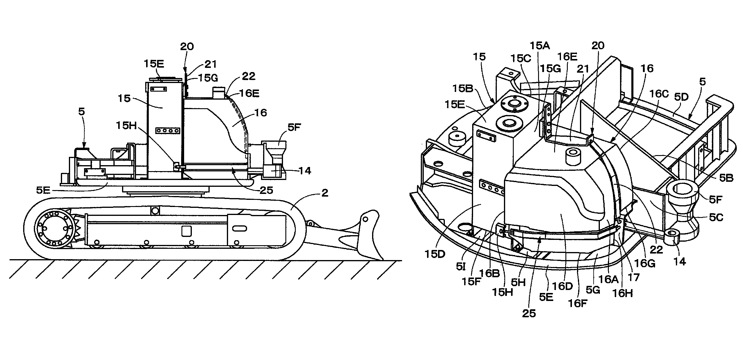
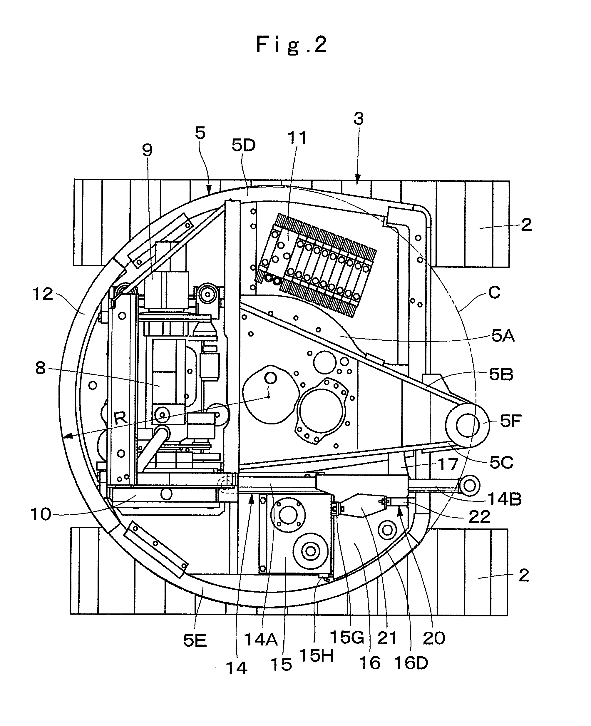
[0038]Subsequently, a configuration of the upper revolving structure 3 will be described. This upper revolving structure 3 is composed of a revolving frame 5, an operator's seat 6, a cab 7, an engine 8, a hydraulic pump 9, a heat exchanger 10, a counterweight 12, an operating oil tank 15, a fuel tank 16 and the like which will be describe...


PUM


Abstract

On a revolving frame (5), an operating oil tank (15) located on the front side of an engine (8) is provided, and a fuel tank (16) located on the front side of the operating oil tank (15) is arranged. A mounting member (17) is provided on the lower side of the fuel tank (16) across a part of a swing cylinder (14). Between the operating oil tank (15) and the mounting member (17), a vertical restraining element (20) for restraining the fuel tank (16) in a front-rear direction and a vertical direction and a lateral restraining element (25) for restraining the fuel tank (16) in a left-right direction are detachably provided. Therefore, the fuel tank (16) can be restrained in two directions, that is, in the horizontal direction and the vertical direction.

Description

TECHNICAL FIELD[0001]The present invention relates to a construction machine such as a hydraulic excavator and particularly to a construction machine provided with a fuel tank on a revolving frame.BACKGROUND ART[0002]In general, a hydraulic excavator which is a typical example of a construction machine is largely constituted by a lower traveling structure, an upper revolving structure rotatably mounted on the lower traveling structure, and a working mechanism provided capable of moving upward / downward on the front side of the upper revolving structure.[0003]The upper revolving structure is largely constituted by a revolving frame, an operator's seat provided on the revolving frame and on which an operator is seated, an engine located on the rear side of the operator's seat and mounted on the revolving frame, a hydraulic pump provided on the engine, an operating oil tank located on the right side of the operator's seat and provided on the revolving frame and storing an operating oil ...

Claims


Application Information

Patent Timeline
Patent Type & Authority Patents(United States)
IPC IPC(8): B62K21/02E02F3/32E02F9/08E02F9/12
CPCE02F9/0883E02F3/32E02F9/08E02F9/12E02F3/325E02F9/0808B60K15/063E02F9/00E02F9/18
Inventor MOTOZU, MAKOTOIRINO, TERUOURASE, KOUHEIUMIZAKI, YUUKISAKO, TOSHIHIRO
Owner NIHON KENKI CO LTD
Why Eureka
Try Eureka