Automotive rear vehicle body structure

a rear vehicle and body technology, applied in the direction of roofs, vehicle arrangements, transportation and packaging, etc., can solve the problems of increased weight, disadvantageous rigidity, increased deformation of members, etc., and achieves enhanced rear impact safety, light weight, and high rigidity

Active Publication Date: 2015-04-07
MAZDA MOTOR CORP
View PDF19 Cites 16 Cited by
  • Summary
  • Abstract
  • Description
  • Claims
  • Application Information

AI Technical Summary

Benefits of technology

[0025]The present invention has been made in view of the above circumstances, and an object thereof is to provide an automotive rear vehicle body structure capable of achieving lighter weight and higher rigidity in a rear subframe, while ensuring an arm length thereof, and enhancing rear impact safety.
[0027]The present invention has an advantageous effect of being able to achieve lighter weight and higher rigidity in the rear subframe, while ensuring an arm length, and enhance rear impact safety.

Problems solved by technology

First, a distance between the front and rear fixing sections 81a, 81b of the side member segment 81 is relatively long and curved. Thus, in order to ensure rigidity against an input of lateral force, it is necessary to increase a plate thickness of the side member segment 81, resulting in an increase in weight.
This causes a problem of an increase in amount of deformation in members around a side sill located forward of the rear side frame 84.
Besides, a distance between the front fixing section 81a and a support section 88a for the front lower arm 88 is relatively long, which is disadvantageous in terms of rigidity.
However, an increase in length of the extension member 86 gives rise to a problem of causing the extension member 86 to more easily undergo deformation, and of increases in required installation space and weight of the extension member 86.
However, as with the conventional structure in FIG. 16, the conventional structure illustrated in FIG. 17 is incapable of shortening a distance between the front fixing section 81a and a support section 88a for the front lower arm 88, which is disadvantageous in terms of rigidity.
However, the rear end of the side member segment 81 is not directly coupled to the rear side frame 84, which is disadvantageous in terms of distribution of a rear impact load.
Moreover, a distance between the front fixing section 81a and a support section 88a for a front lower arm 88 is relatively long, which is disadvantageous in terms of rigidity.
Moreover, a distance between the front fixing section 82a and a support section 88a for the front lower arm 88 is relatively long, which is disadvantageous in terms of rigidity.

Method used


Image

  • Automotive rear vehicle body structure
  • Automotive rear vehicle body structure
  • Automotive rear vehicle body structure

Examples


Embodiment Construction

[0048]Based on the drawings, one embodiment of the present invention will be described in detail.

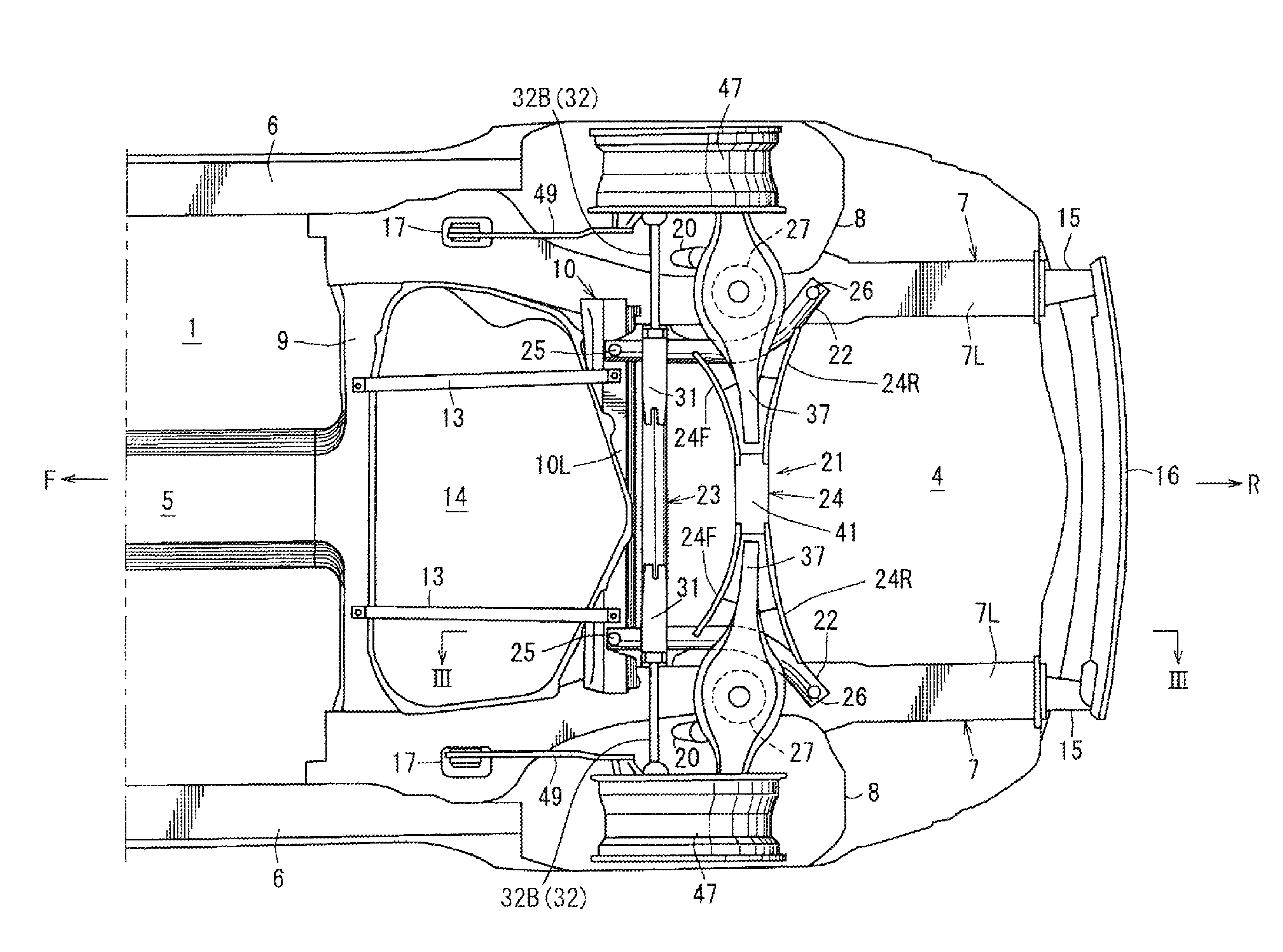
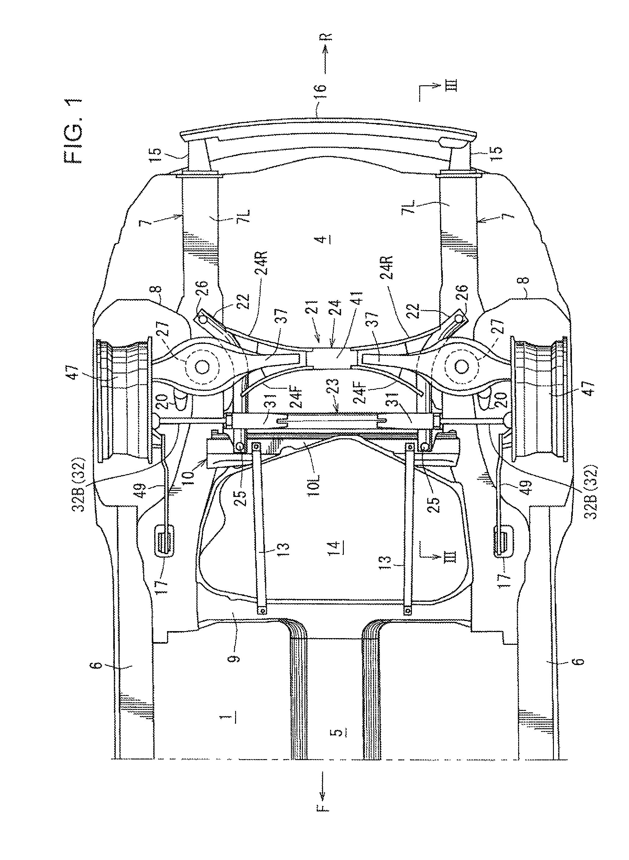
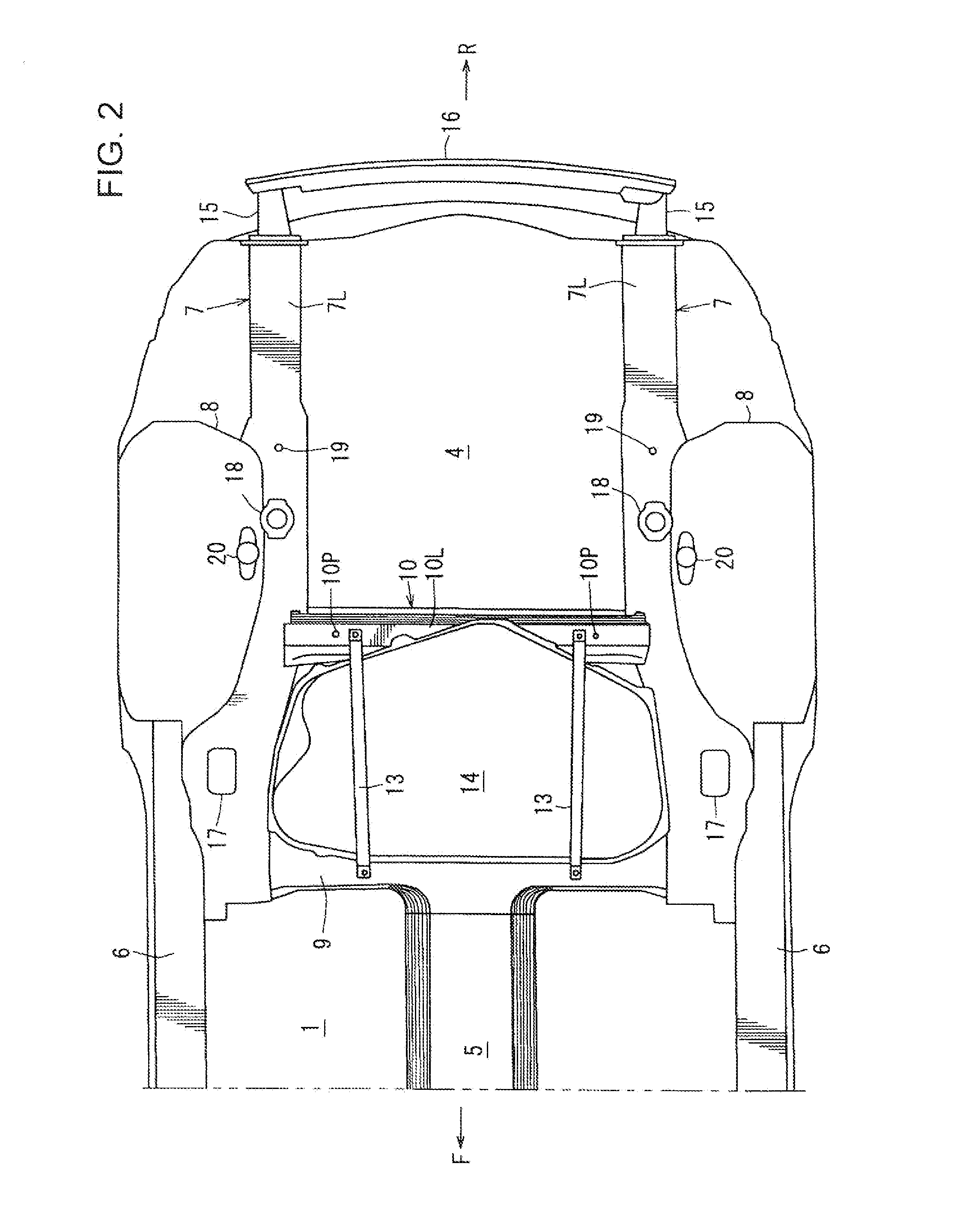
[0049]FIG. 1 is a bottom view illustrating an automotive rear vehicle body structure according to one embodiment of the present invention, and FIG. 2 is a bottom view of a state in which a rear subframe and a suspension arm are removed from the automotive rear vehicle body structure in FIG. 1, and FIG. 3 is a sectional view taken along the arrowed line III-III in FIG. 1, wherein the arrowed line F indicates a forward direction of the vehicle, and the arrowed line R indicates a rearward direction of the vehicle.

[0050]As illustrated primarily in FIGS. 2 and 3, a rear seat pan 2 and a slant section 3 extending obliquely upwardly and rearwardly from a rear edge of the rear seat pan 2 are provided rearward of a center floor panel 1, and further a rear floor 4 is provided rearward of the slant section 3.

[0051]A tunnel section 5 is integrally formed with a vehicle-widthwise central region of a ...


PUM


Abstract

Disclosed is an automotive rear vehicle body structure which comprises a rear subframe (21) provided with right and left side member segments (22). Each of the right and left side member segments (22) has a rear region provided with a rear fixing section (26) attached to a respective one of right and left rear side frames (7), and a front region provided with a front fixing section (25) attached to a vehicle-body cross member (10). A position of the front fixing section (25) of each of the side member segments (22) is set to be located inward of the respective one of the rear side frames (7) in a vehicle width direction, and each of the side member segments (22) is provided with an arm support section (28) configured to pivotally support a suspension arm (32), at a position rearward of the front fixing section (25).

Description

TECHNICAL FIELD[0001]The present invention relates to an automotive rear vehicle body structure comprising a rear subframe having right and left side member segments and front and rear cross member segments.BACKGROUND ART[0002]Generally, a rear subframe (having the same meaning as “rear suspension cross member”) for supporting a rear suspension has right and left side member segments and front and rear cross member segments. As an automotive rear vehicle body structure comprising such a rear subframe, there have been known various structures as illustrated in FIGS. 16 to 20.[0003]A conventional structure (Patent Document 1) schematically illustrated in FIG. 16 in the form of a bottom view comprises a subframe 80 having right and left side member segments 81, 81 and front and rear cross member segments 82, 83, wherein front and rear fixing sections 81a, 81b provided in respective front and rear regions of each of the right and left side member segments 81, 81 are coupled to a respect...

Claims


Application Information

Patent Timeline
Patent Type & Authority Patents(United States)
IPC IPC(8): B60N99/00B62D21/11
CPCB62D21/11B62D25/087B60G7/02B60G2204/15B62D21/155B62D25/08
Inventor OBATA, SATOSHIKITAMURA, MITSUAKI
Owner MAZDA MOTOR CORP
Why Eureka
Try Eureka