Hermaphroditic interconnect system

a technology of hermaphroditic interconnects and connectors, applied in the direction of coupling contact members, coupling device connections, two-part coupling devices, etc., can solve the problems of pin density limitations, pin and socket arrays that do not generally have superior high-frequency data transmission capabilities, and contacts that are quite fragile, so as to avoid stacking tolerance

Active Publication Date: 2015-04-07
OHIO ASSOCD ENTERPRISES
View PDF28 Cites 46 Cited by
  • Summary
  • Abstract
  • Description
  • Claims
  • Application Information

AI Technical Summary

Benefits of technology

[0006]Still another aspect of the invention is the rounded shape of the contact tip outside of the current path. This shape reduces the metal in this critical area and decreases the effect of the “stub”, while minimizing row-to-row coupling.

Problems solved by technology

Also, these pin and socket arrays do not generally have superior high-frequency data transmission capabilities.
Additionally, these pin and socket arrays have pin density limitations unless the mechanical size is made very small, at which time, the contacts are quite fragile.

Method used


Image

  • Hermaphroditic interconnect system
  • Hermaphroditic interconnect system
  • Hermaphroditic interconnect system

Examples


Embodiment Construction

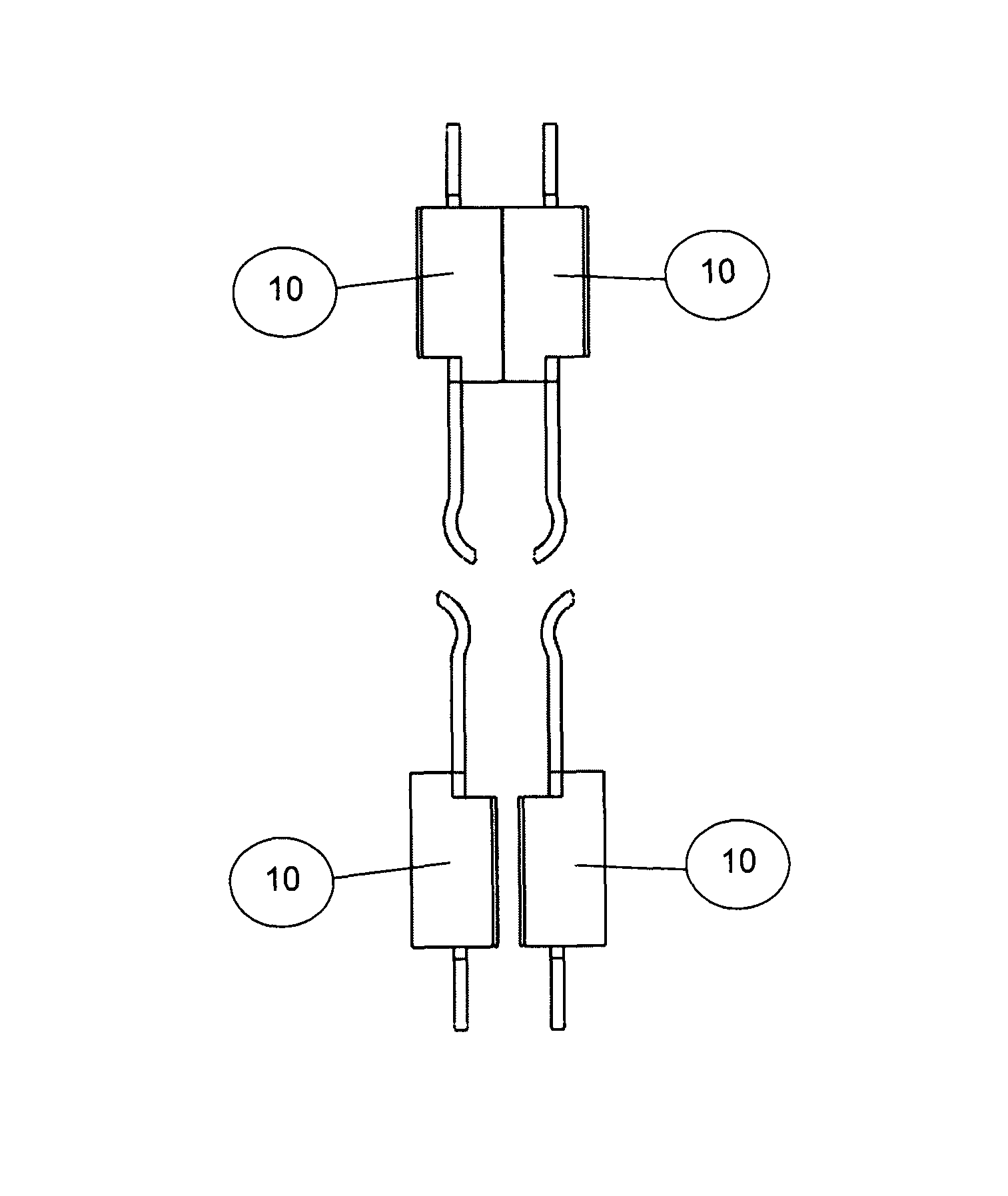
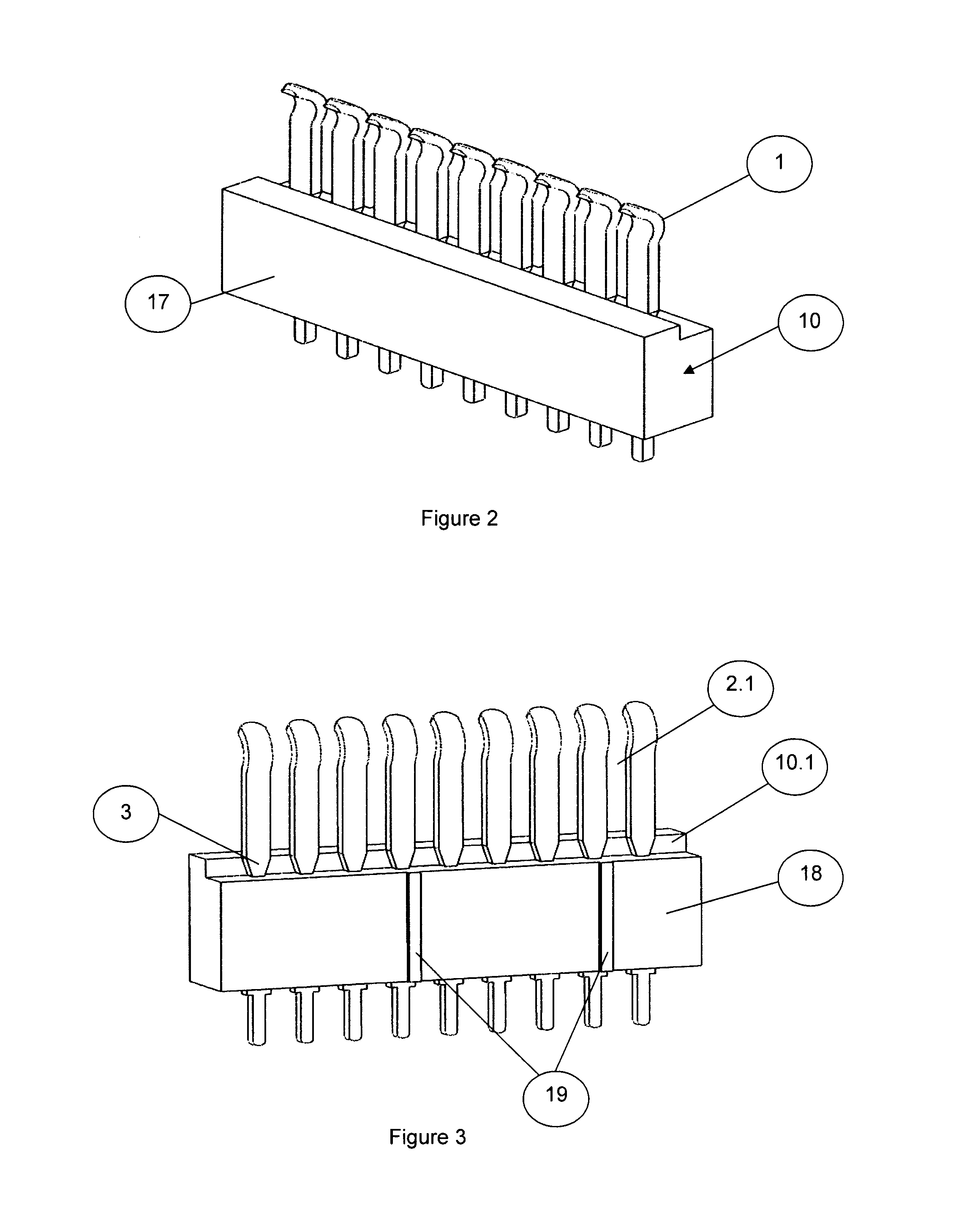
[0048]An electrical interconnect system employs electrical connectors in which the contacts are identical for both the male and the female side of the connection. Contacts are arranged in a linear header and multiple header pairs are arranged in a dielectric matrix or grid. The grid is an external dielectric frame capable of providing load bearing and geometry requirements. This arrangement results in a cost-effective construction that features very high electrical bandwidth capabilities and an extremely rugged product.

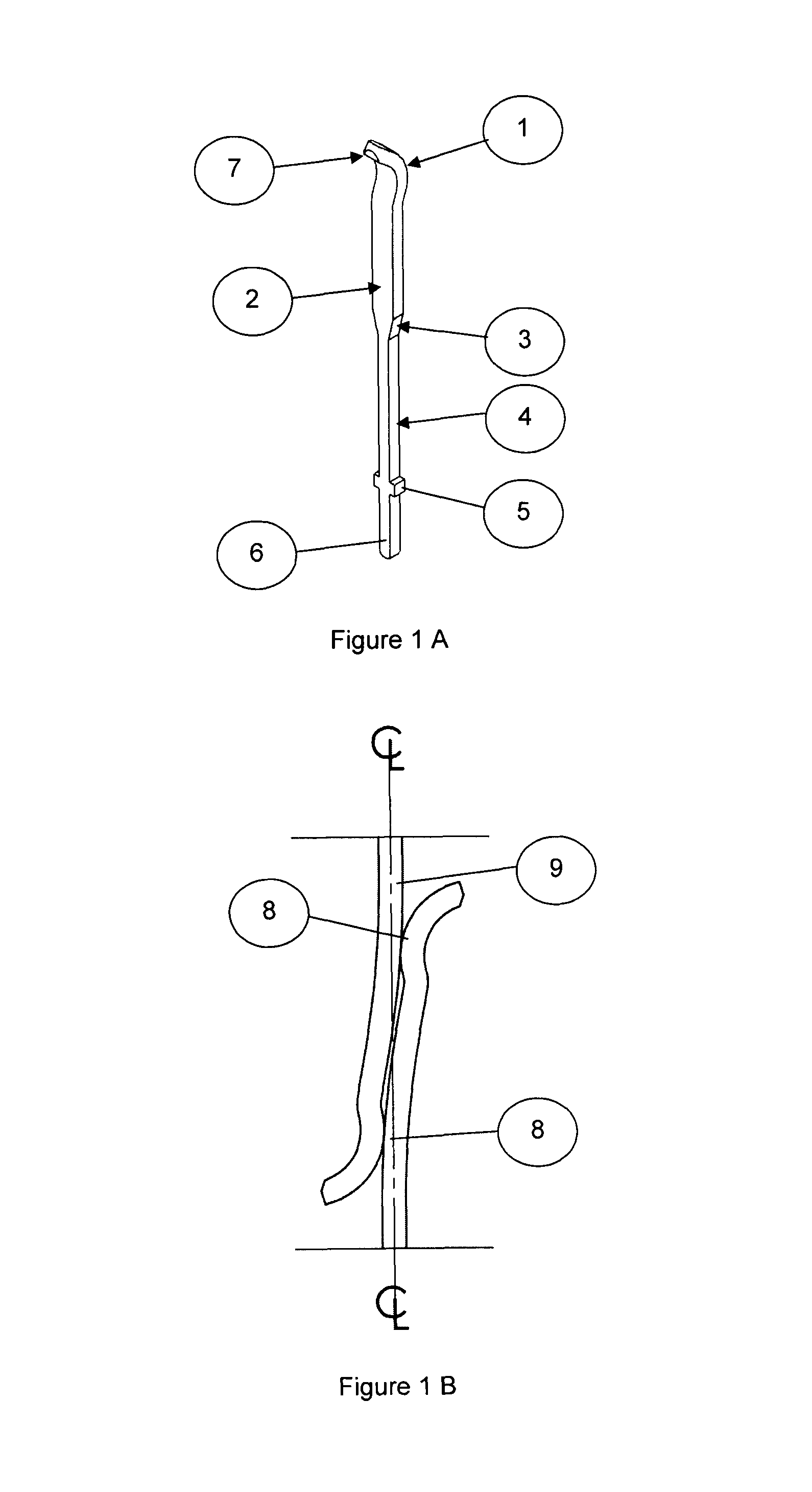
[0049]FIGS. 1A and 1B are examples of a single beam contact. The apex of bend (1) constitutes the primary contact point. The operating beam is shown at (2). Item (3) is a detail that will be explained later. (4) is the continuation of the contact through a dielectric header. Item (5) is a circuit board standoff and impedance corrector. Item (6) is the tail that can be soldered into a circuit board or configured for welding to a cable end. Item (7) is the tip form that...


PUM


Abstract

An electrical interconnect system employs electrical connectors in which the contacts are identical for both the male and the female side of the connection. Contacts are arranged in a linear header and multiple header pairs are arranged in a dielectric matrix or grid. The grid is an external dielectric frame capable of providing load bearing and geometry requirements. This arrangement results in a cost-effective construction that features very high electrical bandwidth capabilities and an extremely rugged product.

Description

[0001]This application claims priority to U.S. Provisional Application 61 / 549,921, filed Oct. 21, 2011, which is incorporated herein by reference in its entirety.BACKGROUND[0002]In the field of rugged, high-reliability connectors, such as military and aerospace connectors, the metal circular shell design is well known. Typically, these shells will house connectors that have a male and female orientation. Generally, on the female side, the contacts are protected by a dielectric shroud, while the male side will be a standing pin array vulnerable to damage by intrusion. Also, these pin and socket arrays do not generally have superior high-frequency data transmission capabilities. Additionally, these pin and socket arrays have pin density limitations unless the mechanical size is made very small, at which time, the contacts are quite fragile.SUMMARY OF THE INVENTION[0003]The present invention seeks to provide a connection scheme in which, at very high-pin density, the connector will hav...

Claims


Application Information

Patent Timeline
Patent Type & Authority Patents(United States)
IPC IPC(8): H01R24/00H01R13/405H01R13/518H01R24/84
CPCH01R24/84H01R13/405H01R13/518H01R13/28
Inventor VANALECK, JOHN TROATH, ALAN L
Owner OHIO ASSOCD ENTERPRISES
Why Eureka
Try Eureka