Method for forming metallic nanowires

a technology of metallic nanowires and nanowires, which is applied in the direction of crystal growth process, liquid/solution decomposition chemical coating, polycrystalline material growth, etc., can solve the problems of low yield of metallic nanowires, limited number and length of metallic nanowires thus formed, and low cost of template materials, etc., to achieve the effect of reducing metal

Active Publication Date: 2011-08-30
NAT CHENG KUNG UNIV
View PDF3 Cites 0 Cited by
  • Summary
  • Abstract
  • Description
  • Claims
  • Application Information

AI Technical Summary

Benefits of technology

[0009]Therefore, an object of the present invention is to provide a method for forming metallic nanowires that can overcome the aforesaid drawbacks associated with the prior art.
[0010]According to an embodiment of the present invention, a method for forming metallic nanowires comprises: (a) providing a substrate formed with a crystal layer thereon; (b) disposing the substrate in such a manner that the crystal layer faces downwardly; (c) applying a metal salt solution, which contains metal ions therein, to the crystal layer of the substrate; and (d) subjecting the metal ions in the metal salt solution on the crystal layer to a heating reduction treatment, thereby resulting in reduced metal that grows downward toward earth's gravity.

Problems solved by technology

The template synthesis method is disadvantageous in that the cost of the template is relatively expensive.
In addition, the number and length of the metallic nanowires thus formed are limited by the nanostructure of the template.
However, the seed-mediated growth method is relatively complex and has a poor control in growing the metallic nanowires.

Method used


Image

  • Method for forming metallic nanowires
  • Method for forming metallic nanowires
  • Method for forming metallic nanowires

Examples


example 1

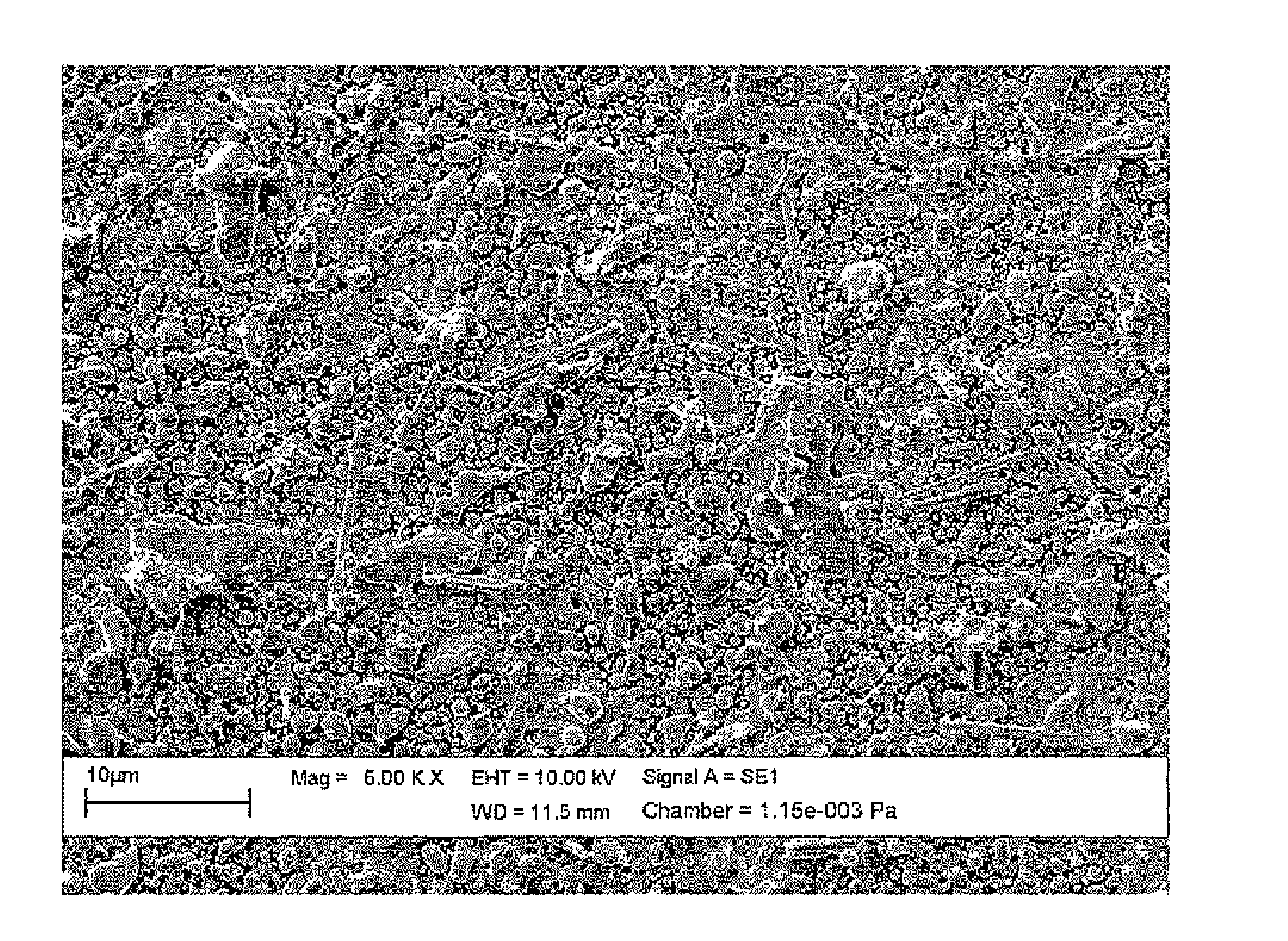
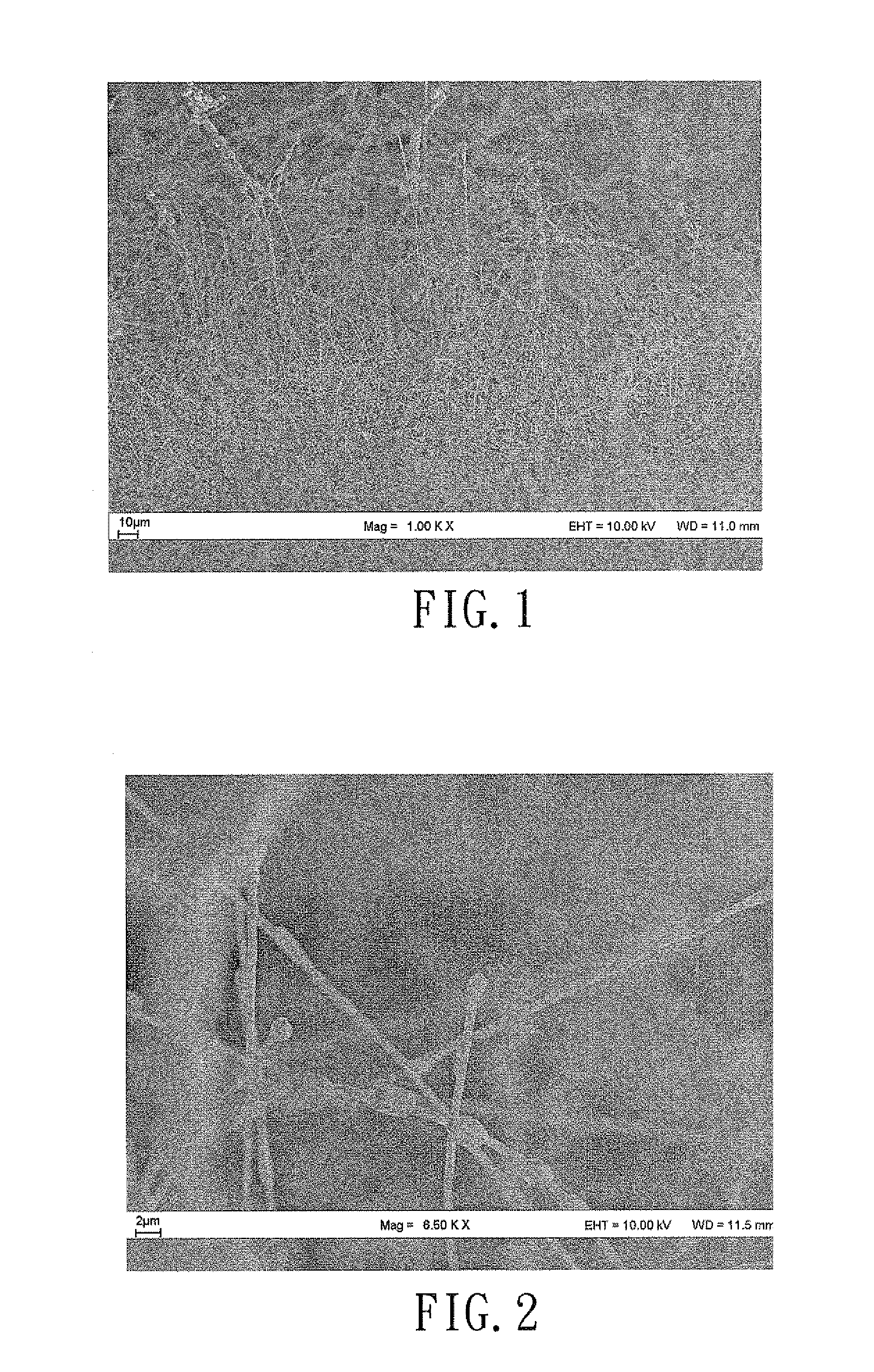
[0028]The metallic nanowires of Example 1 were prepared by the following steps.

[0029]A Si substrate was placed inside a magnetron sputtering system. A feed gas including argon and oxygen was introduced into the system at a 3:7 flow rate ratio to maintain a working pressure of 1.59×10⁻² torr. After applying an output power of 300 W on a Ti target in the magnetron sputtering system, a TiO2 film was formed on the Si substrate. Subsequently, the TiO2 film was heated to a working temperature of 500° C. for 8 hours at a raising rate of 5° C. / min so as to obtain a crystal form of anatase of TiO2 film on the Si substrate. After applying about 15 μL of 0.1 M CuCl2 solution on a 1 cm2 area of the TiO2 film thus formed, the TiO2 film was placed in an oven, and was disposed such that the same faced downwardly. The oven was heated to a working temperature of 300° C. for 2 hours at a raising rate of 5° C. / min. Cu nanowires formed on the TiO2 film were obtained and had an average width of about 10...

example 2

[0031]The metallic nanowires of Example 2 were prepared according to steps similar to those of Example 1, except that this example further utilized a second Si substrate formed with a TiO2 layer thereon. In this example, after application of the metal salt solution on the first Si substrate, two spacers made from quartz and having a height of about 2 mm were disposed on the first Si substrate, and the second Si substrate was then disposed on the spacers such that the TiO2 layers of the first and second substrates faced toward each other, thereby confining and spreading the metal salt solution therebetween.

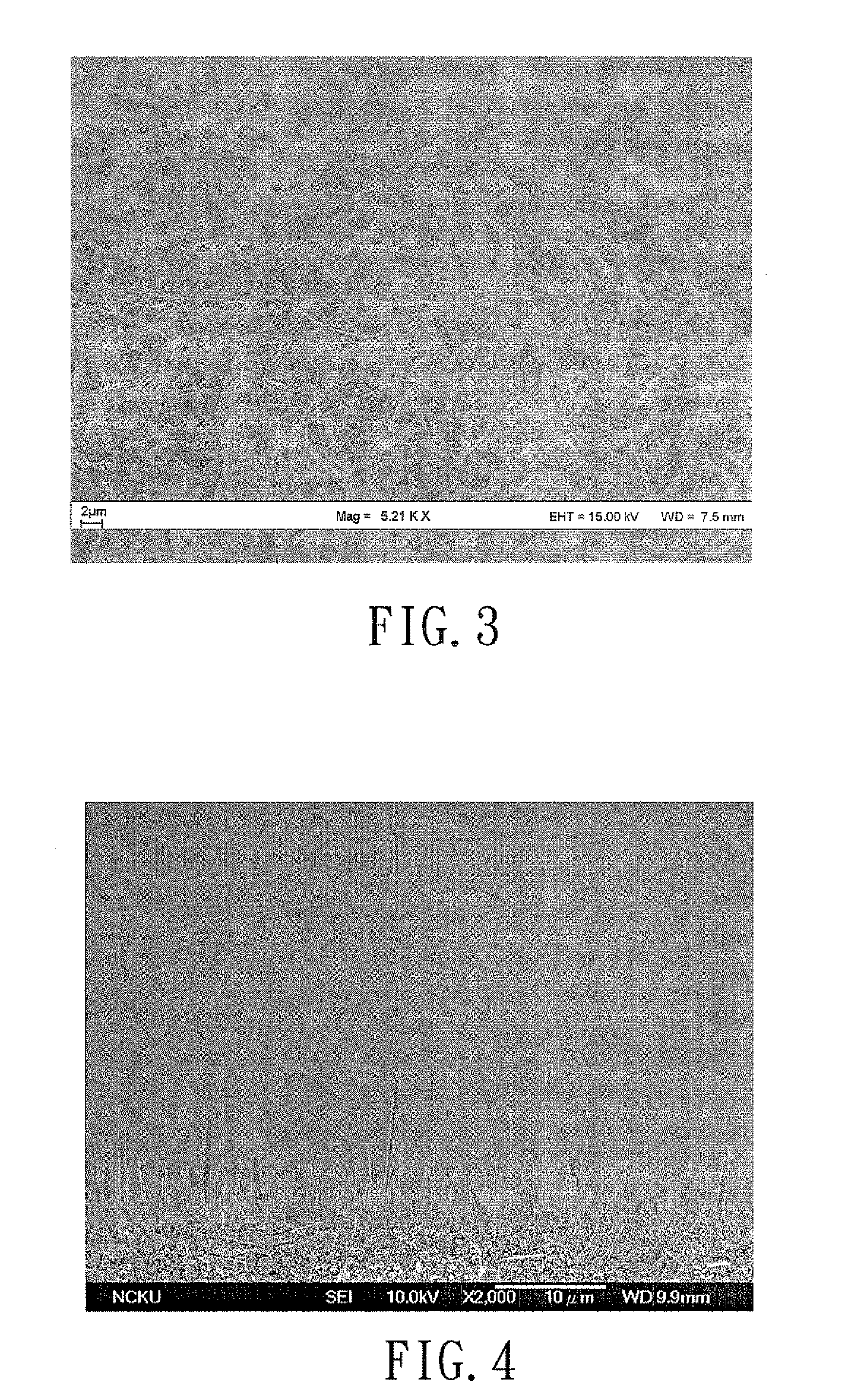
[0032]FIG. 3 is a scanning electron microscope (SEM) image showing the Cu nanowires at 5210× magnification. The Cu nanowires thus formed had an average width of about 100 nm and an average length of about hundreds of micrometers.

example 3

[0033]The metallic nanowires of Example 3 were prepared according to steps similar to those of Example 2, except that the metal salt solution is AgNO3 solution.

[0034]FIGS. 4 and 5 are scanning electron microscope (SEM) images showing the Ag nanowires at 2000× and 5000× magnification, respectively. The Ag nanowires thus formed had an average width of about 100 nm and an average length of about tens of micrometers.


PUM

PropertyMeasurementUnit
temperatureaaaaaaaaaa
distanceaaaaaaaaaa
diameteraaaaaaaaaa

Abstract

A method for forming well-aligned metallic nanowires includes: (a) providing a substrate formed with a crystal layer thereon; (b) disposing the substrate in such a manner that the crystal layer faces downwardly; (c) applying a metal salt solution, which contains metal ions therein, to the crystal layer on the substrate; and (d) subjecting the metal ions in the metal salt solution on the crystal of TiO2 layer to a reduction treatment, thereby resulting in reduced metal that grows downward toward earth's gravity.

Description

CROSS-REFERENCE TO RELATED APPLICATION[0001]This application claims priority of Taiwanese application no. 096110807, filed on Mar. 28, 2007.BACKGROUND OF THE INVENTION[0002]1. Field of the Invention[0003]This invention relates to a method for forming oriented metallic nanowires, more particularly to a method involving growing metallic nanowires by reduction reaction of metal salt solutions in a downward direction toward earth's gravity.[0004]2. Description of the Related Art[0005]Conventional methods for forming metallic nanowires include the template synthesis method, the seed-mediated growth method, and the thermal-induced forming method.[0006]In the template synthesis method, a porous material, such as anodic alumina membrane (AAM), SiO2 and zeolite, formed with a plurality of nano-sized pores therein is used as a template such that metallic nanowires are grown in the nano-sized pores. Formation of the metallic nanowires in the nano-sized pores can be conducted through soft chemi...

Claims


Application Information

Patent Timeline
Patent Type & Authority Patents(United States)
IPC IPC(8): B05D3/02
CPCC23C14/083C23C14/5806C23C18/06C30B7/14C30B29/02C30B29/62
Inventor CHEN, IN-GANNSONG, JENN-MINGTUNG, HSIEN-TSE
Owner NAT CHENG KUNG UNIV
Why Eureka
Try Eureka