
Stereo image display device that is capable of making a stereo image recognized based on a right-eye image and a left-eye image

a display device and stereo image technology, applied in static indicating devices, instruments, optical elements, etc., can solve the problems of inconvenient user calibration, high sensitivity of optical sensors, adverse influence of devices, etc., to suppress stereo image discomfort, highly accurate adjustment of chromaticity, and suppress the effect of chromaticity differen

Active Publication Date: 2015-04-07
EIZO
View PDF15 Cites 1 Cited by
  • Summary
  • Abstract
  • Description
  • Claims
  • Application Information

AI Technical Summary

Benefits of technology

The present invention aims to provide a device for displaying stereo images that reduces the discomfort caused by the use of a semi-transparent mirror and improves calibration flexibility. The device allows for separate calibration of each display means, which increases the flexibility of the calibration environment. This ensures that the calibration optical sensor and other components are in close contact with the display means, leading to improved calibration accuracy.

Problems solved by technology

However, in the case of the conventional examples having the above configuration, the following problems exist.
In the conventional former device, the display portion is separate from the optical sensor, and thereby the device is suffered from the adverse influence of the disturbance, such as the ambient light.
Thereby, it is inconvenient for the user to execute the calibration, and also the optical sensor needs to be highly sensitive because the distance between the display portion and the optical sensor is long.
Therefore, the former device is not practical.
However, even when the calibration is executed with the calibration coefficients obtained at each of the first display portion and the second display portion, the chromaticity and luminance between the left-eye image and the right-eye image at the viewpoint become unbalanced due to a reflection characteristic and a transmittance characteristic of the semi-transparent mirror.
As a result, even the latter device may cause uncomfortable feeling of the stereo image disadvantageously.

Method used


Image

  • Stereo image display device that is capable of making a stereo image recognized based on a right-eye image and a left-eye image
  • Stereo image display device that is capable of making a stereo image recognized based on a right-eye image and a left-eye image
  • Stereo image display device that is capable of making a stereo image recognized based on a right-eye image and a left-eye image

Examples


Embodiment Construction

[0105]One embodiment of the present invention will be described below with reference to accompanying drawings.

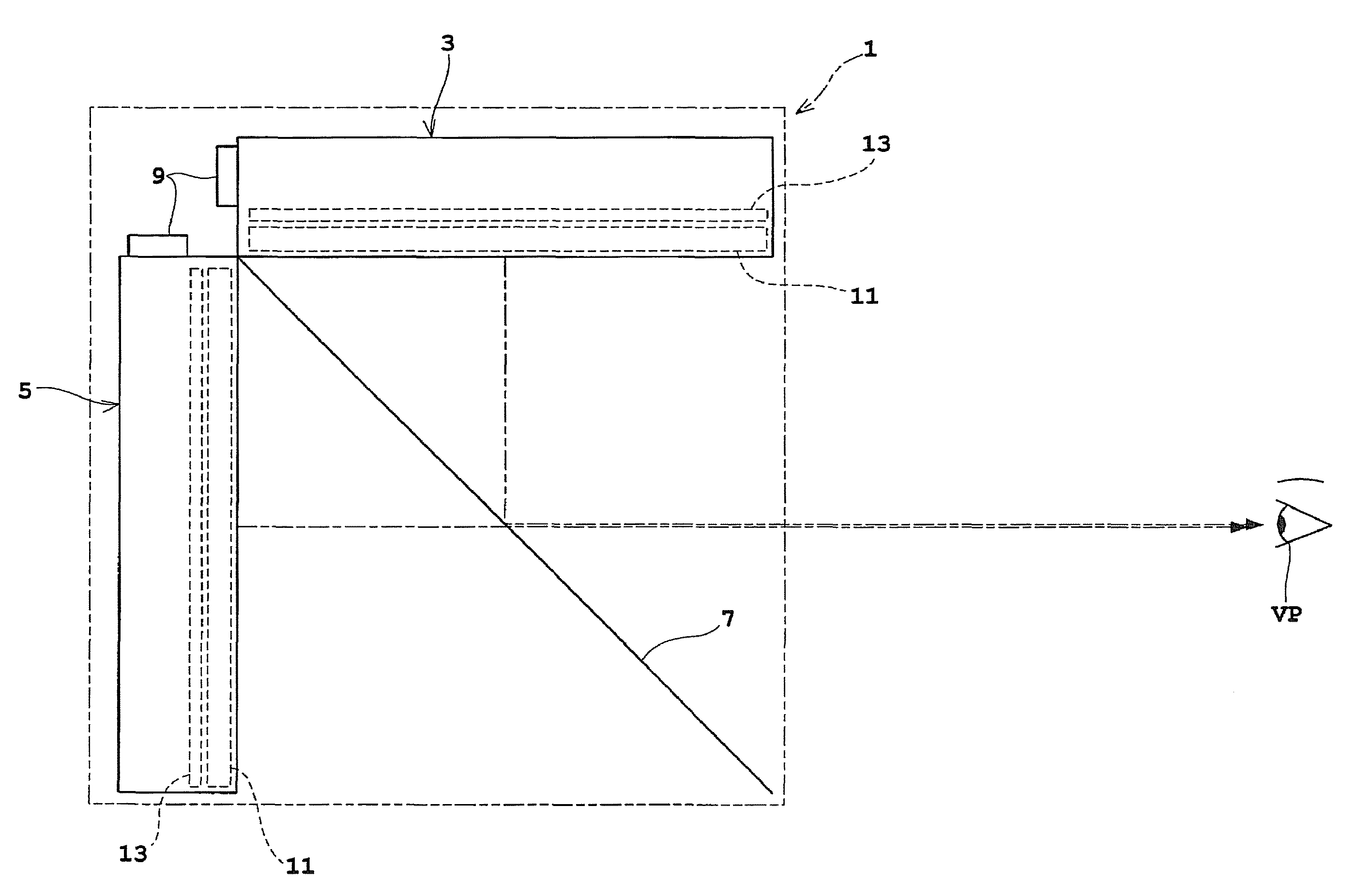
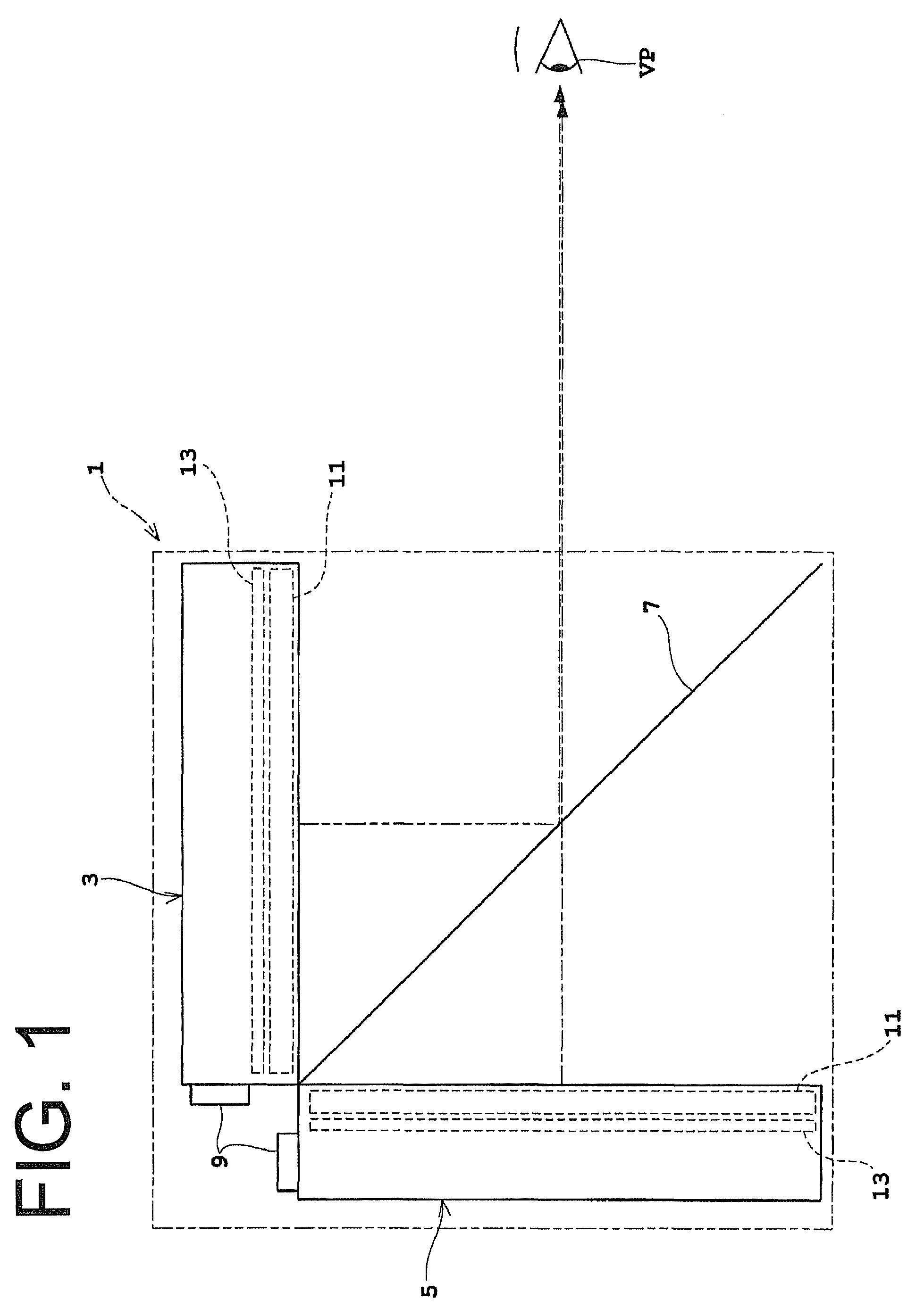
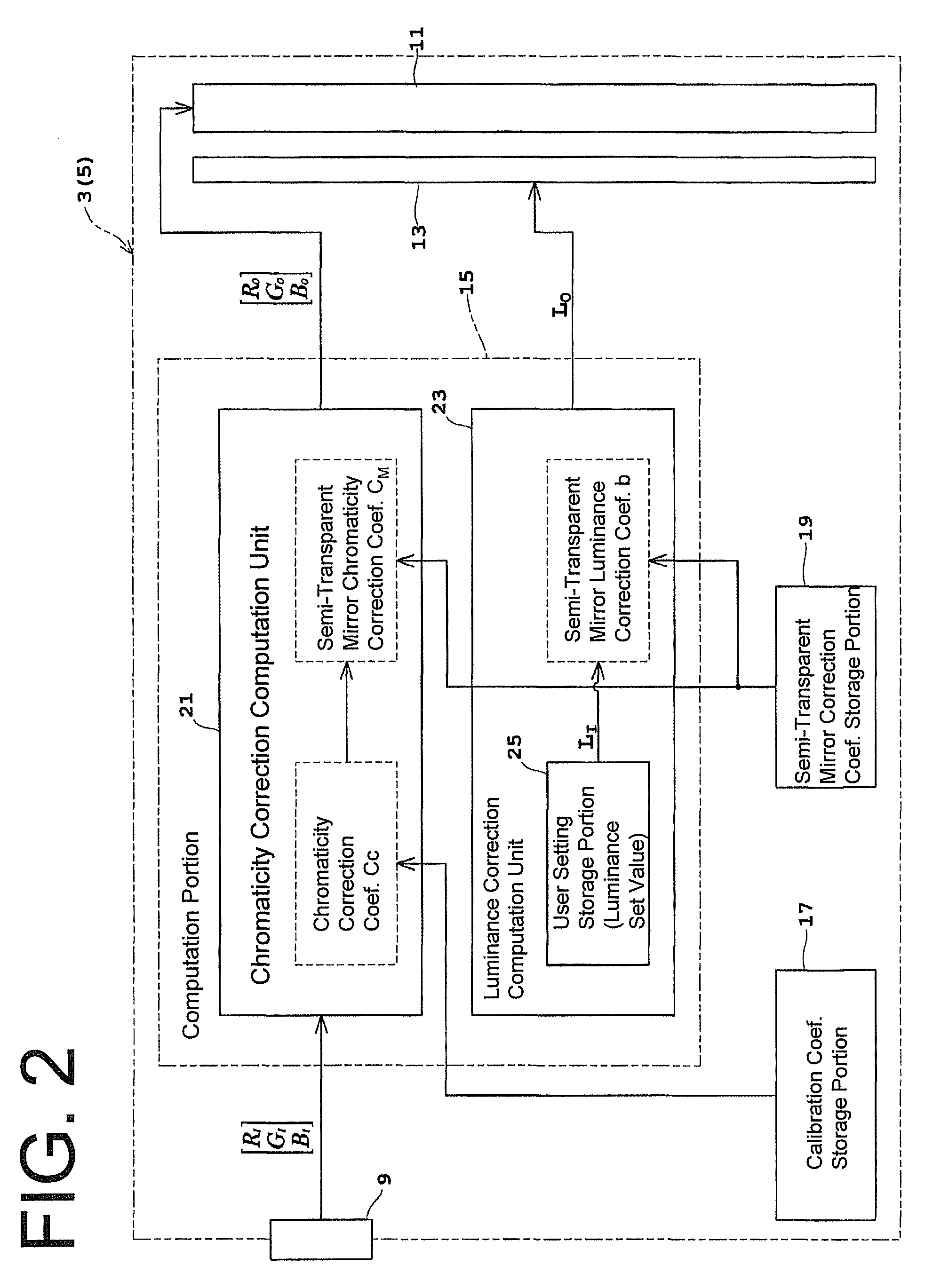
[0106]FIG. 1 is a side view illustrating a schematic configuration of a stereo image display device according to the embodiment, and FIG. 2 is a block diagram illustrating a schematic configuration of a first image display portion.

[0107]A stereo image display device 1 according to the present embodiment has function of allowing an observer at a viewpoint VP to observe a stereo image based on a binocular parallax.

[0108]The stereo image display device 1 includes a first image display portion 3, a second image display portion 5, and a semi-transparent mirror 7. In the embodiment, the first image display portion 3 is provided in a substantially horizontal position with an image screen facing downwardly. The second image display portion 5 is provided in a standing position with an image screen extending in a vertical direction on a back side of the first image display portion 3 w...


PUM


Abstract

A luminance correction computation unit 23 corrects a luminance input signal LI, which is inputted into a first luminance adjustment portion 13, to LO based on the semi-transparent mirror luminance correction coefficient b, and the luminance correction computation unit 23 corrects a luminance input signal LI, which is inputted into a second luminance adjustment portion 13, to LO based on the semi-transparent mirror luminance correction coefficient b. As a result, an image of the first image display portion 3, which is reflected by a semi-transparent mirror, and an image of the second image display portion, which is allowed to transmit through the semi-transparent mirror, are corrected in order to cancel a luminance difference according to an optical characteristic of the semi-transparent mirror.

Description

CROSS-REFERENCE TO RELATED APPLICATIONS[0001]This application is a National Phase of PCT International Patent Application No. PCT / JP2010 / 001559, filed Mar. 5, 2010, which claims the benefit of Japanese Patent Application Nos. 2009-117617 and 2009-273223, filed May 14, 2009 and Dec. 1, 2009, respectively, in the Japanese Patent Office, the disclosures of which are incorporated herein by reference.BACKGROUND OF THE INVENTION[0002]1. Field of the Invention[0003]The present invention relates to a stereo image display device that is capable of making a stereo image recognized based on a right-eye image and a left-eye image, and specially relates to a technique that enables binocular vision through a semi-transparent mirror.[0004]2. Description of the Related Art[0005]Conventionally, a device of the above type may be a stereo image display device, which includes, for example, a first display portion configured to display a first image serving as a left-eye image, a second display portion ...

Claims


Application Information

Patent Timeline
Patent Type & Authority Patents(United States)
IPC IPC(8): H04N13/04G02B27/22G02B30/25G03B35/20G09G3/00G09G3/34G09G5/02G09G5/06H04N13/00
CPCG03B35/20G02B27/2235G02B27/26G09G3/003H04N13/0025H04N13/0443G09G2320/0233G09G2360/16G09G3/3406G09G5/02G09G5/06G09G2340/06G02B30/25G02B30/35H04N13/133H04N13/346
Inventor YABUI, TOMOHIKOKITAYAMA, HIDEKIHAYASHI, AKINORIMATSUNAMI, KATSUHIKOISOBE, NAOSHI
Owner EIZO
Learn More