Supercharge Your Innovation With Domain-Expert AI Agents!

Cleave holder, an assembly, and methods for cleaving ends of optical fibers and securing them to a multi-optical fiber connector module

a technology of optical fiber and connector module, applied in the field of optical communication, can solve the problems of unacceptable bit error rate (ber), insufficient precision of optical alignment along the optical pathway to prevent unacceptable optical loss

Active Publication Date: 2015-04-07
AVAGO TECH INT SALES PTE LTD
View PDF40 Cites 4 Cited by
  • Summary
  • Abstract
  • Description
  • Claims
  • Application Information

AI Technical Summary

Benefits of technology

The solution enables precise stripping, cleaving, and securement of optical fibers, reducing signal degradation and manufacturing costs by maintaining precise optical alignment and eliminating the need for costly polishing processes.

Problems solved by technology

Unacceptable optical losses lead to signal degradation, which can lead to an unacceptable bit error rate (BER).
Otherwise, the optical alignment along the optical pathways will not have sufficient precision to prevent unacceptable optical losses from occurring.
The process of polishing the ends of the fibers is time consuming and expensive.
It can be difficult to strip and cleave fibers with precision, especially in cases where loose fibers are used instead of ribbons.
Although tools exist for stripping and cleaving fibers, such tools are often not easy to use with precision.
In addition, once the ends of the optical fibers have been stripped and cleaved, it can be difficult to secure them to a connector module at precise locations.

Method used


Image

  • Cleave holder, an assembly, and methods for cleaving ends of optical fibers and securing them to a multi-optical fiber connector module
  • Cleave holder, an assembly, and methods for cleaving ends of optical fibers and securing them to a multi-optical fiber connector module
  • Cleave holder, an assembly, and methods for cleaving ends of optical fibers and securing them to a multi-optical fiber connector module

Examples


Embodiment Construction

[0030]In accordance with embodiments of the invention, a cleave holder is provided that allows the ends of optical fibers to be precisely stripped and cleaved and then secured at precise locations in a multi-optical fiber connector module. Prior to describing the cleave holder and the methods and systems for stripping and cleaving fiber ends and securing them to a multi-fiber connector module, illustrative embodiments of a multi-fiber connector module with which the cleave holder may be suitable used will be described with reference to FIGS. 1-11B. Illustrative embodiments of the cleave holder and the methods and systems of the invention will then be described with reference to FIGS. 12-16. Like reference numbers in the figures represent like elements, features, or components. The features in the drawings are not necessarily drawn to scale.

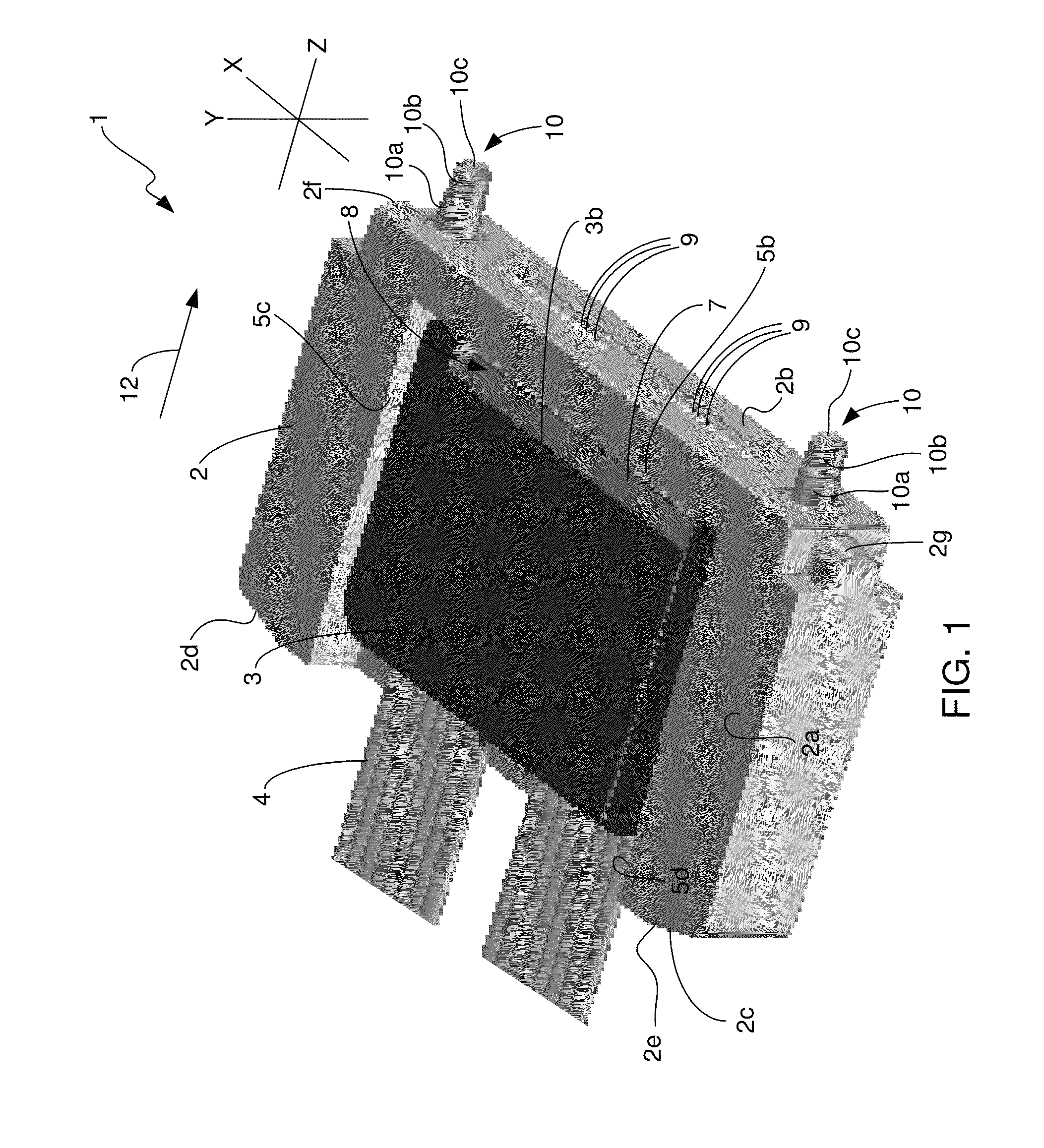
[0031]FIG. 1 illustrates a side perspective view of the multi-optical fiber connector module 1 in accordance with an illustrative embodiment. The...


PUM

PropertyMeasurementUnit
lengthaaaaaaaaaa
optical alignmentaaaaaaaaaa
optical lossesaaaaaaaaaa

Abstract

A cleave holder is provided that allows the ends of optical fibers to be precisely stripped and cleaved and then secured at precise locations in a multi-optical fiber connector module. The cleave holder is secured to length-wise portions of optical fibers that extend through the cleave holder. The cleave holder has reference holes formed in its lower surface that allow it to be mounted on a fixture having pins on it that mate with the reference holes. Once the ends of the fibers have been stripped and cleaved, the cleaved ends are secured to precise locations within a connector module. The cleave holder and the connector module form an assembly that can be used together, with the cleave holder acting as a mounting structure for the assembly and as a strain relief mechanism.

Description

TECHNICAL FIELD OF THE INVENTION[0001]The invention relates to optical communications. More particularly, the invention relates to a cleave holder, an assembly, and methods for cleaving ends of optical fibers and securing them to a multi-optical fiber connector module.BACKGROUND OF THE INVENTION[0002]Multi-optical fiber connector modules are used to mechanically couple the ends of a plurality of optical fibers to a parallel optical communications module that has a plurality of optical channels. The parallel optical communications module may be a parallel optical transceiver module having both transmit and receive optical channels, a parallel optical transmitter module having only transmit optical channels, or a parallel optical receiver module having only receive optical channels. A typical multi-optical fiber connector module includes an optics system that couples light between the ends of the optical fibers and respective optoelectronic devices that are contained within the parall...

Claims


Application Information

Patent Timeline
Patent Type & Authority Patents(United States)
IPC IPC(8): G02B6/00G02B6/25G02B6/38
CPCG02B6/3839G02B6/25G02B6/3865Y10T29/49826
Inventor MCCOLLOCH, LAURENCE R.
Owner AVAGO TECH INT SALES PTE LTD
Features
  • R&D
  • Intellectual Property
  • Life Sciences
  • Materials
  • Tech Scout
  • Unparalleled Data Quality
  • Higher Quality Content
  • 60% Fewer Hallucinations
Learn More