Concrete anchor bolt fastener and tool and method for installing

Inactive Publication Date: 2015-04-14
DIFANTE AGOSTINO
View PDF1 Cites 8 Cited by
  • Summary
  • Abstract
  • Description
  • Claims
  • Application Information

AI Technical Summary

Benefits of technology

The present invention is a tool for forming tapered anchor bore holes in concrete surfaces. The tool includes a cutting tool with a rotary cutting head and an elongated drive shaft. The cutting head is positioned below the bottom circular end plate of the fixture guide cylinder and is attached to the drive shaft. The drive shaft extends upwardly through the circular guide hole and the rectangular guide slot of the fixture base plate. A collar is attached to the drive shaft to limit its motion. The fixture base plate has at least one indexing guide to secure it in a known direction. The technical effects of this invention are a tool that facilitates the creation of tapered anchor bore holes in concrete surfaces with accuracy and ease.

Problems solved by technology

Although prior art expansion type concrete anchor bolt fasteners of the type described above are reasonably effective, the uniform diameter of a concrete bore hole in which the anchor bolt sleeve is installed does not have any abutting surfaces which positively resist tensional forces exerted on the upper end of the bolt that could pull the bolt upwards in the bore hole.
Therefore, such prior art concrete anchor bolts can and sometimes do work free from their anchored location in a concrete support structure, and are therefor problematic.

Method used


Image

  • Concrete anchor bolt fastener and tool and method for installing
  • Concrete anchor bolt fastener and tool and method for installing
  • Concrete anchor bolt fastener and tool and method for installing

Examples


embodiment 50

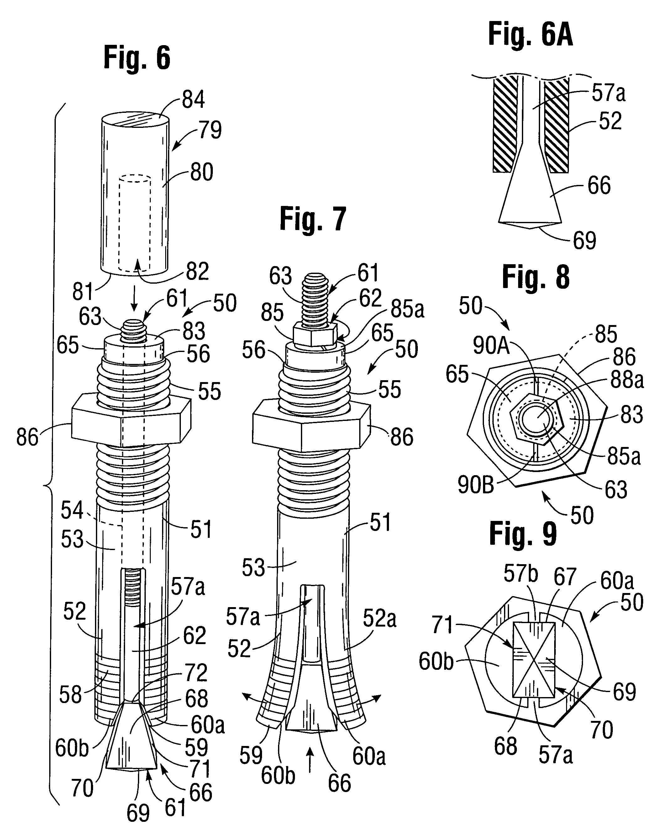
[0070]As shown in FIG. 6, an impact-type embodiment 50 of a novel concrete anchor bolt fastener according to the present invention includes a longitudinally elongated tubular metal body 51, which preferably is fabricated from the shank of a steel bolt. Body 51 has a lower expandable slotted section 52 which has smooth or preferably ridged outer walls 53. As shown in FIGS. 6 and 9, lower slotted section 52 of fastener body 51 has a uniform diameter circular cross-section and a uniform diameter, circular bore 54 which extends through the entire length of the body. As shown in FIG. 6, body 51 of fastener 50 has an upper externally helically threaded section 55 which is axially aligned with lower section 52. Upper threaded section 55 of body 51 is a coaxially aligned extension of lower section 51, and has an upper transverse annular end wall 56 which is coextensive with upper end wall of body 51.

[0071]As shown in FIGS. 6 and 9, lower expandable slotted section 52 of fastener 50 has at l...

embodiment 150

[0096]FIGS. 27-30 illustrate an alternate embodiment 150 of a concrete anchor bolt fastener which is a modification of the impact installable fastener 50 shown in FIGS. 6-9 and described above. Modified concrete anchor bolt fastener 150 is similar to impact installable fastener 50, but is installed by exerting torque on fastener components, rather than exerting impact forces. Thus, as shown in FIG. 28, fastener 150 has an expander head 166 which is tensioned upwardly to thus wedge outwardly against and thus deform outwardly bolt legs 160A, 160B. This tensioning is effected by using a wrench to tighten a hex nut 185 downwardly onto the upper surface of a milled polygonal cross-section bearing collar head 165 located at the upper end of fastener 150 and thus onto the upper annular end wall 156 of an upper externally threaded section 155 of fastener body 151. This tightening action in turn exerts an upward tensional force directed on the threaded upper end 163 of expander shaft 162, th...


PUM

PropertyMeasurementUnit
Thicknessaaaaaaaaaa
Shapeaaaaaaaaaa
Frictionaaaaaaaaaa

Abstract

A method for attaching an article to a hardened concrete body includes a tool that has a slotted base plate and a downwardly depending slotted guide cylinder having at the lower end thereof a circular end plate which has a central aperture, insertable into a bore hole to support a rotatably driven shaft disposed through the slot, guide cylinder, and central aperture through said end plate and having at its lower end a cutting head, the shaft being pushed downwardly into the bore and rocked back and forth in the slot, causing the cutting head to form an oval enlargement at the base of the bore hole. An anchor bolt fastener according to the invention is then inserted into the bore hole, the fastener including an elongated shank which has a central shaft bore slidably holding a shaft having at its lower end an expander wedge forcible upwards into a slot extending into a lower end face of the shank to thus expand bolt legs on opposite sides of the slot into the oval bore hole enlargement.

Description

BACKGROUND OF THE INVENTION[0001]A. Field of the Invention[0002]The present invention relates to fasteners for anchoring objects to concrete bodies such as pediments and precast concrete walls. More particularly, the invention relates to a novel anchor bolt fastener for installation in precast and poured concrete structures, a novel tool and method for cutting a specially shaped hole in hardened concrete which is adapted to receive the novel fastener and a method for installing the fastener in the hole.[0003]B. Description of Background Art[0004]there are a wide variety of applications in which it is necessary to install a fastener in a concrete structure after the concrete has been poured and hardened. For example bolts or threaded studs protruding perpendicularly from a concrete pediment, base or wall are installed to support vertically disposed street light standards, power poles or the like, or horizontally disposed structures such as floor beams or posts.[0005]Typical prior art...

Claims


Application Information

Patent Timeline
IPC IPC(8): B23P11/00B25B21/00
CPCB25B21/002B23B51/0027B23B2226/75F16B13/065Y10T29/49948
Inventor DIFANTE, AGOSTINO
Owner DIFANTE AGOSTINO
Why Eureka
Try Eureka