Female screw component and fastening component utilizing the same

a technology of female threads and components, applied in the direction of threaded fasteners, fastening means, screws, etc., can solve the problems of difficult reverse rotation of the bolt, seizing, and male threads of the bolts not properly engaging with the female threads of the female threads, so as to reduce the size of the non-thread space, prevent seizing, and enhance the function of the projection for guiding the male threads

Inactive Publication Date: 2015-04-14
AOYAMA SEISAKUSHO CO LTD +1
View PDF17 Cites 6 Cited by
  • Summary
  • Abstract
  • Description
  • Claims
  • Application Information

AI Technical Summary

Benefits of technology

[0013]According to the female thread member of the invention, the projection is formed on the non-thread portion formed on the bolt-inserting side of the female thread member body at the location in the line extending from the helical line of the female thread. Hence, when the bolt is inclinedly inserted from the side where the projection is formed, the male thread of the bolt normally threadedly engages with the female thread of the female thread member due to the same reason as shown in FIG. 2, and the stand-up surfaces at the thread ridge-leading ends of the bolt and the female thread member do not bump against each other.
[0014]In addition, when the bolt is inclinedly inserted from a side opposite to the projection, since at least one pitch of the thread other than the projection is the non-thread portion having no female thread, the tip end of the male thread of the bolt is inserted without coming into contact with the female thread of the female thread member, and the tip end first engages with the projection. Hence, the male thread normally threadedly engages with the female thread of the female thread member likewise, and the stand-up surfaces at the thread ridge-leading ends of the bolt and the female thread member do not bump against each other. Further, the projection does not have a portion corresponding to the incomplete thread portion or even if the projection has such a portion, it can extremely be shortened and thus, it is possible to completely prevent the seizing caused by the inclined insertion.
[0015]If the position of the leading end of the female thread of the female thread member body and the position of the leading end of the projection are deviated from each other in the circumferential direction, it is possible to reduce a size of the non-thread space formed on the bolt-inserting side in the female thread member body as compared with a structure in which the positions of the leading ends match with each other. Therefore, the function of the projection for guiding the male thread is enhanced, and the inclination of the bolt can be corrected more easily.

Problems solved by technology

At that time, if the bolt is inserted from an inclined direction with respect to an axis of the female thread member, a male thread of the bolt does not properly engage with a female thread of the female thread member.
In this situation, if the bolt is forcedly rotated by an electric tool or the like, seizing may occur.
If such a state occurs, it also becomes difficult to reversely rotate the bolt and a serious problem occurs.
However, if a bolt having no incomplete thread portion is fastened to such a female thread member, it is found that stand-up surfaces of the bolt and the female thread member at thread ridge-leading ends bump against each other depending upon the inclination direction of the bolt with respect to the axis of the female thread member, and the bolt can not smoothly be inserted in some cases.
Further, when the bolt is inserted from a direction of 3 o'clock position or 9 o'clock position, there is also a possibility that the stand-up surfaces at the thread ridge-leading ends will bump against each other.
Therefore, it is found the problem that the leading end surfaces bump against each other depending upon the inserting direction of the bolt cannot be solved merely by forming the cutting-start portion of the female thread into the stand-up surface and by eliminating the incomplete thread portion.

Method used


Image

  • Female screw component and fastening component utilizing the same
  • Female screw component and fastening component utilizing the same
  • Female screw component and fastening component utilizing the same

Examples


Embodiment Construction

[0029]Embodiments of the present invention will be described below.

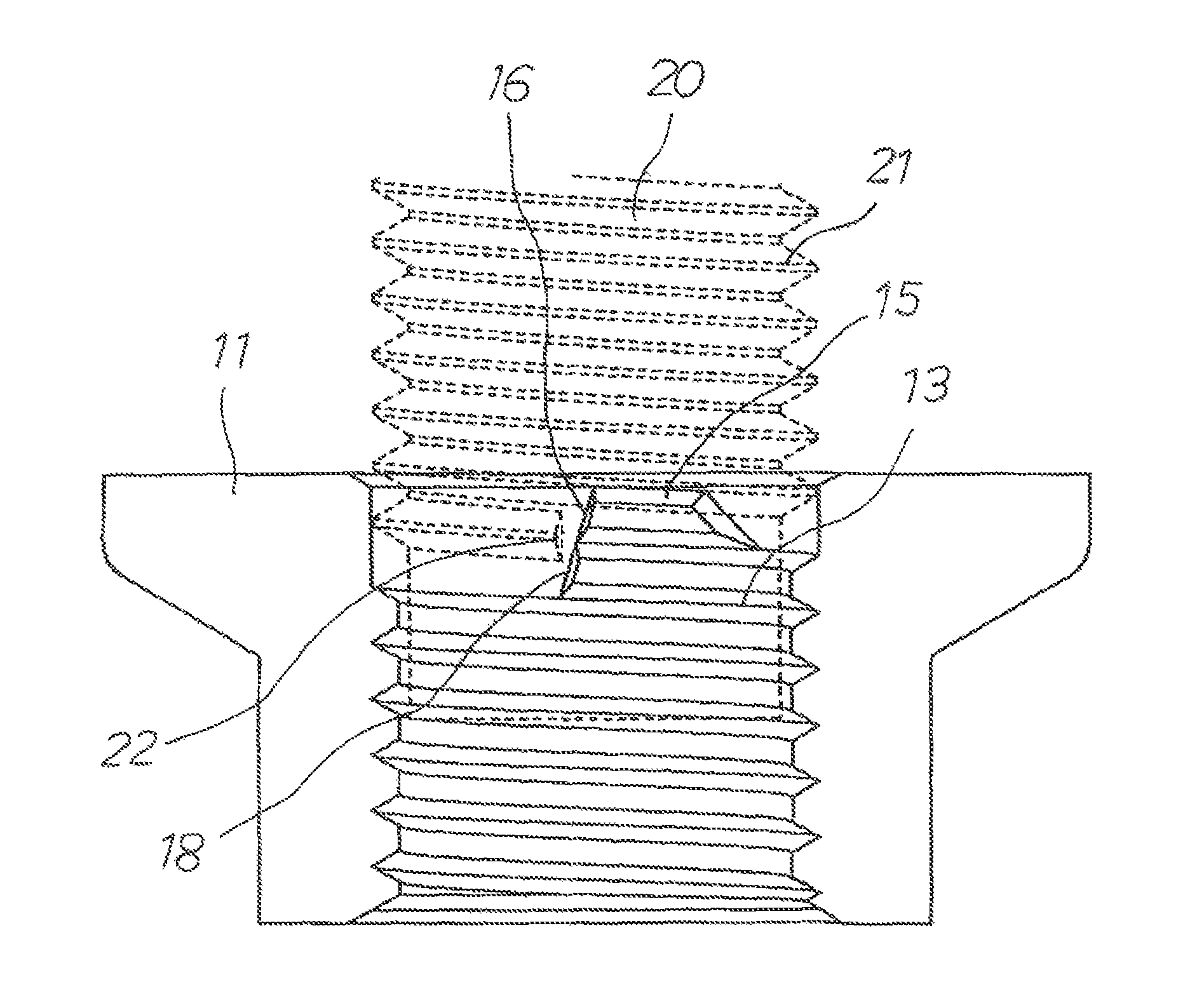
[0030]FIG. 4 is a perspective view showing an embodiment in which the present invention is applied to a weld nut which is a female thread member. FIG. 5 is an enlarged view of an essential portion thereof. FIG. 6 is a sectional view taken along the line A-A. FIG. 7 is a sectional view taken along the line B-B. A reference number 10 represents a female thread member body, a reference number 11 represents an end surface (seat surface) thereof on a bolt-inserting side, and a reference number 12 represents a welding projection formed on the end surface 11. Although a female thread 13 is formed in an inner peripheral surface of the female thread member body 10, at least one pitch from the end surface 11 is formed as a non-thread portion 14 having no female thread 13.

[0031]A projection 15 which engages with a flank surface of a male thread of the bolt is formed on the non-thread portion 14. It is necessary that the project...


PUM


Abstract

A female thread member capable of preventing seizing caused by inclined insertion, and being smoothly fastened from any directions in which a bolt is inserted, and a fastening member using the female thread member. A non-thread portion is formed on an inner peripheral surface of a female thread member body having a female thread for a length corresponding to at least one pitch from an end surface on a bolt-inserting side, and a projection which comes into contact with a flank surface of a male thread of an inserted bolt is formed on a line extending from a helical line of the female thread. The female thread member is used in combination with the bolt having no incomplete thread portion, and there is no adverse possibility of seizing regardless of any directions in which the bolt is inserted.

Description

BACKGROUND OF THE INVENTION[0001]1. Field of the Invention[0002]The present invention relates to, a female thread member used for fastening various components, and to a fastening member using the female thread member.[0003]2. Description of the Related Art[0004]For example, in an assembling process of automobiles, there is widely employed a fastening method in which a female thread member such as a nut is welded to one of components and the other component is fixed by a bolt. At that time, if the bolt is inserted from an inclined direction with respect to an axis of the female thread member, a male thread of the bolt does not properly engage with a female thread of the female thread member. Thus, thread ridges of the male and the female threads bump against each other. In this situation, if the bolt is forcedly rotated by an electric tool or the like, seizing may occur. If such a state occurs, it also becomes difficult to reversely rotate the bolt and a serious problem occurs.[0005]...

Claims


Application Information

Patent Timeline
Patent Type & Authority Patents(United States)
IPC IPC(8): F16B37/00F16B35/04
CPCF16B35/047F16B37/00F16B33/02
Inventor TOYONAGA, SEIICHIFUJIURA, SATOSHIKOUGUCHI, KOUICHIROUMURASE, YOSHIHIROKONAGAYA, SATOSHIIWATA, MASAHITOHASEGAWA, SADAYOSHI
Owner AOYAMA SEISAKUSHO CO LTD
Why Eureka
Try Eureka