Ball-type tensioner

a tensioner and ball-type technology, applied in the direction of belts/chains/gearings, mechanical equipment, etc., can solve the problems of excessive tension in the timing chain over a long time, affecting the performance of the timing chain, so as to reduce the “flip-flop” noise, block the retracting displacement of the plunger, and eliminate the effect of “whirring”

Inactive Publication Date: 2013-04-16
TSUBAKIMOTO CHAIN CO
View PDF3 Cites 3 Cited by
  • Summary
  • Abstract
  • Description
  • Claims
  • Application Information

AI Technical Summary

Benefits of technology

[0009]An aim of the invention is to solve the above-described problems by providing a ball-type tensioner that has one or more of the following effects. First, it reduces “flip-flop” noises by blocking retracting displacement of the plunger caused by forces applied to the plunger by a timing chain on starting an engine after the engine has been inoperative for a long time. Second, it eliminates the “beat note” generated by excessive chain tension caused by excessive protrusion of the plunger during operation of the engine, by permitting retracting displacement of the plunger. Third, it prevents seizure of the plunger. Finally the tensioner is simple, easy to assemble, and exhibits excellent durability.
[0011]The ball-type tensioner according to the invention is simple and easily manufactured and exhibits excellent durability. In addition, it can reduce “flip-flop” noises that occur on engine start-up by blocking retraction of the plunger when the engine is started after having been out of operation for a long time. Blocking of retraction of the plunger is achieved because the balls of the tensioner are sandwiched between the steep rear face of a rack tooth on the plunger and the inclined bottom surfaces of the ball-guiding grooves in the annular ball seat, while still in contact with the gradually sloping forward face of a rack tooth on the plunger.
[0012]When the chain tension drops as the timing chain becomes loose and the plunger protrudes, the balls, which are in contact with the gradually sloping forward face of a rack tooth, are pushed radially outward, and cause the annular ball seat to move in the retracting direction. At this time the balls are no longer sandwiched between the steep rear face of a rack tooth on the plunger and the inclined bottom surfaces of the ball-guiding grooves. The balls can then cross over a tooth of the rack permitting the plunger to advance. After crossing a tooth, the balls are pushed radially inward by the inclined surfaces of the ball-guiding groove and toward a gradually sloping forward face of another rack tooth, whereupon the balls are again sandwiched between the steep rear face of another rack tooth on the plunger and the inclined bottom surfaces of the ball-guiding grooves, and the plunger is latched in a more advanced position. The advancing displacement of the plunger thus balances the chain tension in a repeating series of operations, ensuring optimal tension in the timing chain.
[0013]If excessive chain tension occurs when the plunger is an excessively protruding condition, the force exerted through the balls by the steeply sloped rearward side of a rack tooth pushes the annular ball seat rearward, away from the sealing plate in the retracting direction. The balls move outward and cross over one rack tooth, whereupon the balls are pushed inward and against a gradually sloping forward face of a next rack tooth and again sandwiched again between a steep rearward face of a rank tooth and the inclined bottom surfaces of the annular ball seat. By a series of repetitions of this operation, the plunger can be made to retract. Seizing of the plunger can thereby be prevented and the “beat note” or “whirring” noise that is generated by increased chain tension when the plunger is in an excessively protruding condition can be eliminated.
[0014]In a preferred embodiment, the slopes of the forward and rearward surfaces of the rack teeth are sufficiently steep that the center of a ball disposed between a rearward surface and an adjacent forward surface of rack tooth is always within the annular groove. Because the centers of the balls always reside within the annular groove in the wall of the plunger-accommodating hole, the balls always roll between a steeply sloping rear face of an annular rack tooth on the plunger and the inclined bottom surfaces of the annular ball seat without falling out of the annular groove. Accordingly, it is possible to achieve quick and steady response to increases and decreases in chain tension.
[0015]The annular ball seat preferably has at least three ball-guiding grooves formed therein, and the ball-guiding grooves in the annular ball seat are disposed at uniform intervals around the ball seat. The use of at least three uniformly spaced bell-guiding grooves makes it possible to eliminate eccentric radial loads as the plunger advances and retracts. Accordingly, the forces acting on the annular ball seat are equally dispersed, the plunger can advance and retract smoothly in response to changes in chain tension, and the useful life of the annular ball seat can be extended.

Problems solved by technology

However, in some cases, when the plunger has protruded excessively, the ratchet pawl can cause the plunger 520 to remain in the excessively protruded condition and thereby apply an excessive force to the timing chain, causing a so-called “beat note” or “whirring” noise.
Another problem is that the plunger 520 in tensioner 500 can seize, causing excessive tension in the timing chain over a long time.
The resulting eccentric tooth engagement can result in excessive loads causing chipping of the ratchet teeth or the teeth of the pawl.
Such chipping can quickly lead to failure of the ratchet mechanism.

Method used


Image

  • Ball-type tensioner
  • Ball-type tensioner
  • Ball-type tensioner

Examples


Embodiment Construction

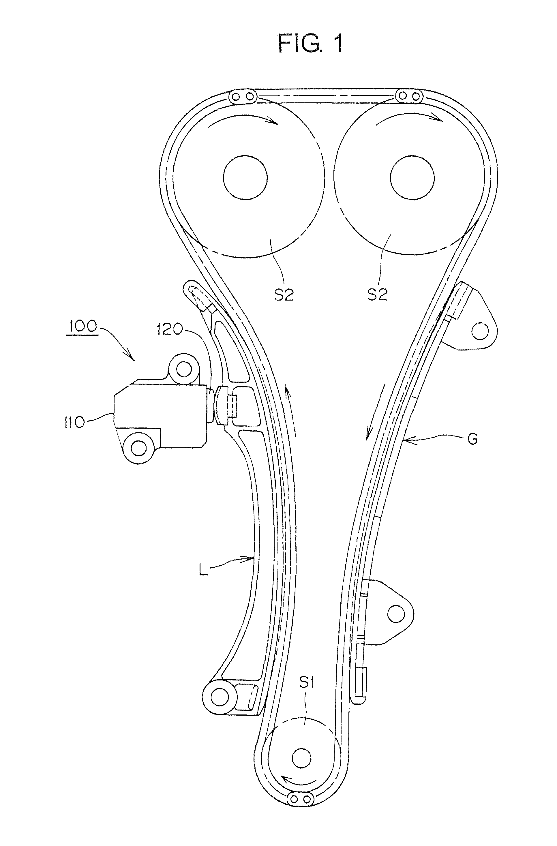
[0030]As shown in FIG. 1, a ball-type tensioner 100, which is mounted on an dual overhead cam (DOHC) internal combustion engine (not shown) is disposed adjacent the slack side of a timing chain C, which is driven by a crankshaft sprocket S1 end in driving relationship camshaft sprockets S2. The protruding plunger 120 of tensioner 100 engages a pivoted lever L, which, in turn, applies tension to the slack-side of the timing chain C.

[0031]A stationary guide G, mounted on the engine, guides the tension side of the timing chain C.

[0032]An arrow on crankshaft sprocket S1 indicates the direction of its rotation. When the crankshaft sprocket rotates, the timing chain C travels in the direction indicated by arrows adjacent the chain, causing the camshaft the sprockets S2 to rotate.

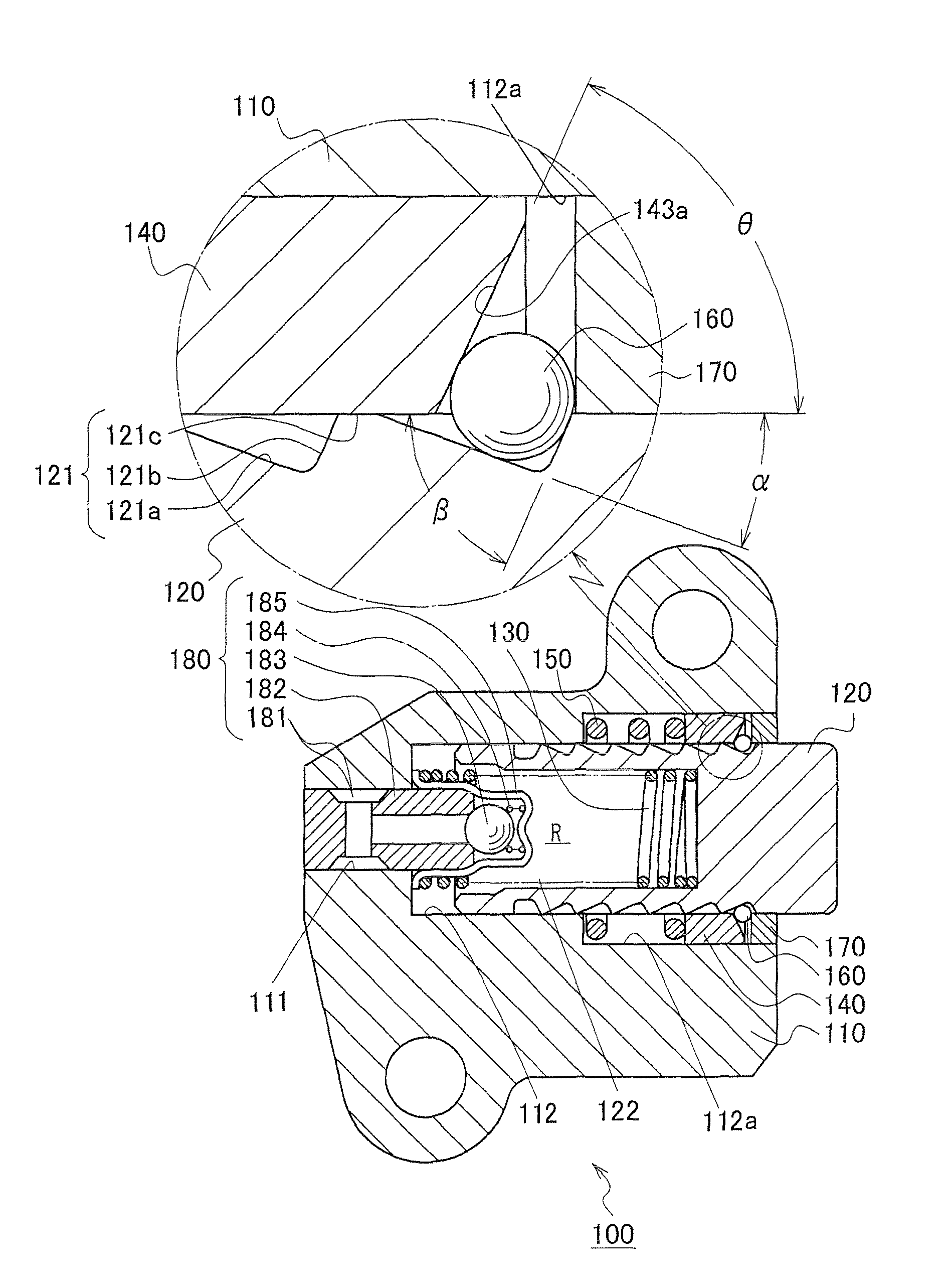
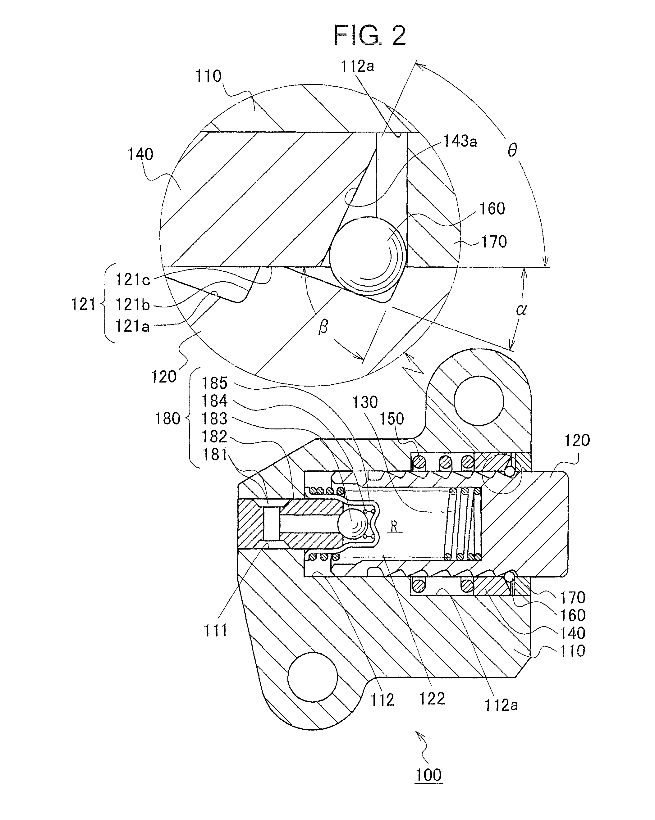
[0033]As shown in FIG. 2, the housing 110 of tensioner 100 has an oil supply passage 111 for introducing oil supplied under pressure through an engine block from an oil pump (not shown). The housing has a plunger-...


PUM


Abstract

A tensioner for a chain or similar power transmission medium comprises a spring-biased plunger having annular rack teeth with gradually sloping forward surfaces and steeper rearward surfaces. The teeth are engaged by radially movable balls received in inclined grooves in an axially movable annular ball seat disposed in an annular groove formed in the wall of a plunger-accommodating hole in a tensioner housing. The bottoms of the inclined grooves face a steep rearward surface of a rack tooth, and the annular ball seat is axially movable in the annular groove and biased in the plunger protruding direction by a spring that exerts a biasing force greater than the biasing force exerted on the plunger. The balls and the movable annular ball seat block retraction of the plunger on engine start-up, but permit retraction when excessive force is imparted to the plunger while the plunger is in a protruding condition.

Description

CROSS REFERENCE TO RELATED APPLICATIONS[0001]This application claims priority on the basis of Japanese Patent Application 2010-103812, filed on Apr. 28, 2010. The disclosure of Japanese Patent Application 2010-103812 is incorporated by reference.FIELD OF THE INVENTION[0002]The invention relates to a ball-type tensioner for applying tension to a timing chain for driving a camshaft and, optionally, other components of an engine.BACKGROUND OF THE INVENTION[0003]In a typical tensioner for maintaining tension in an engine timing chain, a plunger for exerting the tensioning force protrudes from a plunger-accommodating hole in a tensioner housing, and is slidable in the plunger-accommodating hole. The plunger is biased in the protruding direction by a plunger-biasing spring and by hydraulic pressure exerted by oil in a high pressure oil chamber formed by the plunger and the tensioner housing.[0004]FIG. 13 shows a typical prior art tensioner 500, referred to as a “ratchet type tensioner.” A...

Claims


Application Information

Patent Timeline
Patent Type & Authority Patents(United States)
IPC IPC(8): F16H7/08
CPCF16H7/0848F16H2007/0806F16H2007/0859F16H2007/0853F16H2007/0812
Inventor YOSHIDA, OSAMUKUREMATSU, YUJIHAYAMI, ATSUSHI
Owner TSUBAKIMOTO CHAIN CO
Why Eureka
Try Eureka