

Getter structure including a gas-permeable material description
a technology of getter structure and gas-permeable material, which is applied in the direction of fluid speed measurement, separation process, instruments, etc., can solve the problem of complicating the production of the device including such a getter structur
- Summary
- Abstract
- Description
- Claims
- Application Information
AI Technical Summary
Benefits of technology
Problems solved by technology
Method used
Image

Examples
first embodiment
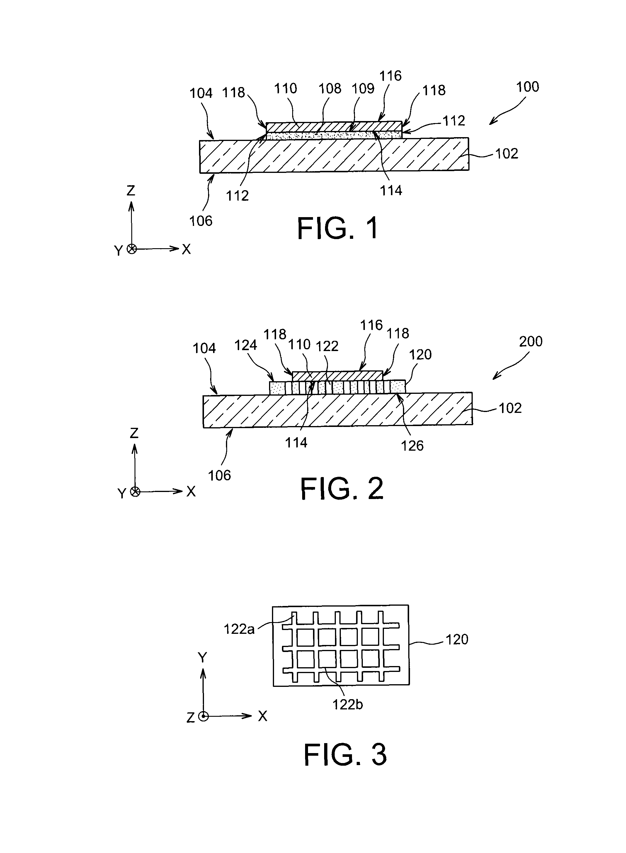
[0045]Reference is firstly made to FIG. 1, which represents a getter structure 100 according to a
[0046]Getter structure 100 includes a support 102, for example a semiconductor layer, including two main faces 104 and 106. The structure 100 also includes a portion 108 of gas-permeable material, formed on one of the main faces 104 of the support 102. This gas-permeability of the material of the portion 108 is obtained in this case due to the fact that the material of the portion 108, for example SiOC deposited by cathodic sputtering on the support 102, is porous in nature. As a variant, such a portion of porous material 108 may be formed by vapor deposition of SiO2, as described in document “Nanostructured porous SiO2 films for antireflection coatings” by K. M. A Sobahan et al., Optics Communication, Volume 284, Issue 3, February 2011, pages 873-876, or by a metal deposition of the ZrO2 type by vapor deposition, as described in document “Some approaches to producing microporous materia...
second embodiment
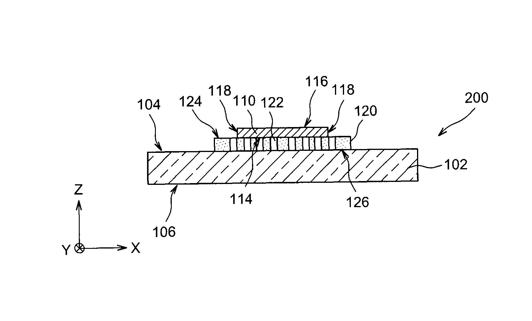
[0057]FIG. 2 represents a getter structure 200 according to a
[0058]Like the previously described getter structure 100, the getter structure 200 includes the support 102, together with the portion of getter material 110 which is positioned on the face 104 of the support 102 through a portion 120 of gas-permeable material. However, unlike the portion of porous material 108 of the getter structure 100, the gas permeability of the portion 120 is not obtained through the intrinsic porosity of the material used (portion 120 is, for example, SiO2-based), but is obtained due to a structuring of a dense network of channels 122 produced in the portion of material 120. These channels 122, which are for example obtained through the implementation of photolithography and etching steps, in this case traverse the portion 120 all the way through (where this thickness is, for example, between approximately 1 μm and 10 μm), from a front face 124 to a rear face 126 of the portion 120.
[0059]FIG. 3 repr...
third embodiment
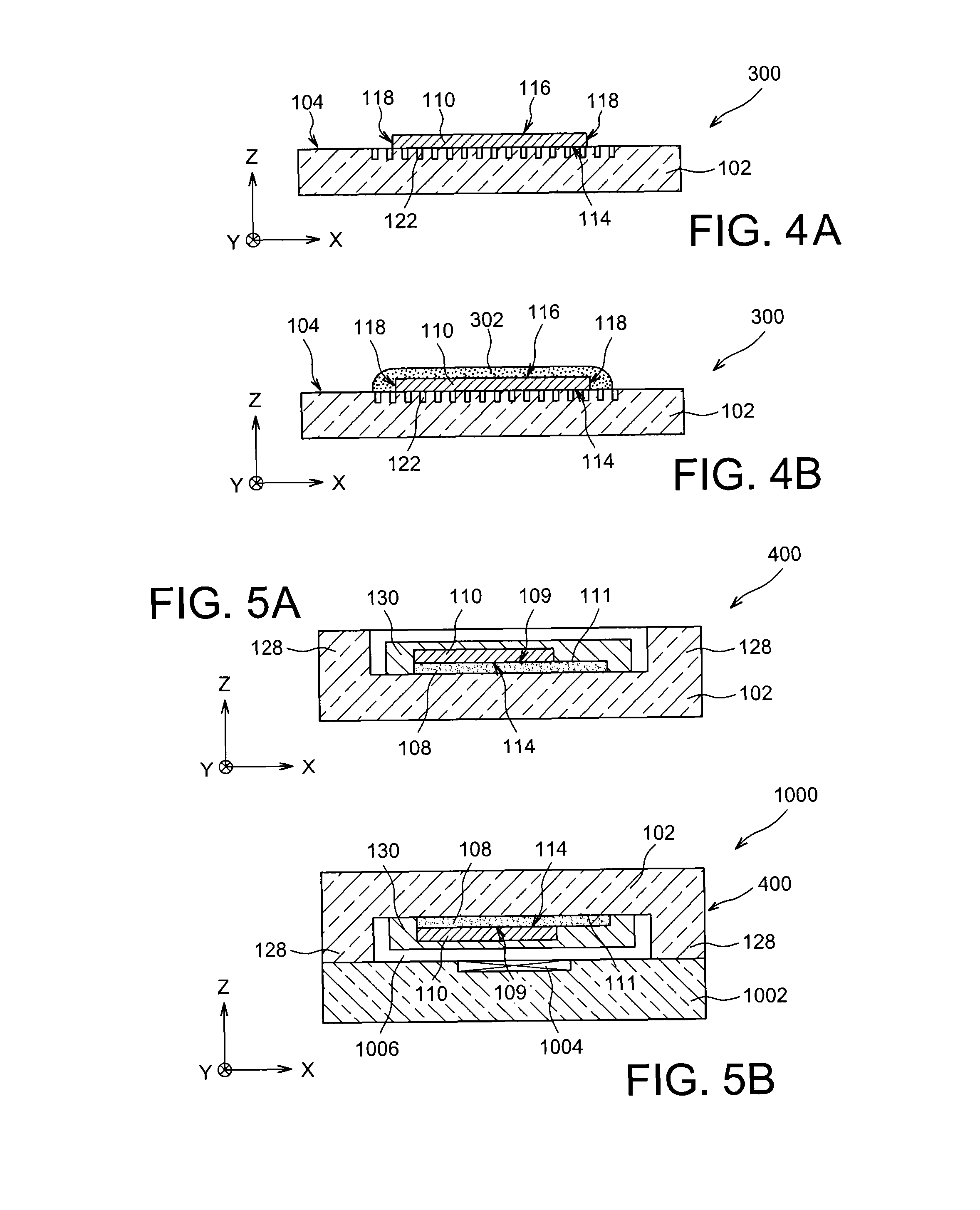
[0063]FIG. 4A represents a getter structure 300 according to a
[0064]Getter structure 300 includes the portion of getter material 110 which in this case is positioned directly on the front face 104 of the support 102, i.e. against this face 104. In this case, the channels 122 are produced in the support 102, at the level of its front face 104. In this third embodiment, the channels 122 are produced only part way through the support 102.
[0065]The part of the support 102 including the channels 122 therefore forms a portion of gas-permeable material.
[0066]The gas-permeability function achieved by the channels 122 of this getter structure 300 is similar to the one produced by the channels 122 of the previously described getter structure 200. A part of channels 122 is not covered by the portion of getter material 110. The pattern (for example a grid) and / or the dimensions of the channels 122 of the getter structure 200 may be similar to the pattern and / or dimensions of the channels 122 of...
PUM
| Property | Measurement | Unit |
|---|---|---|
| diameter | aaaaa | aaaaa |
| diameter | aaaaa | aaaaa |
| diameter | aaaaa | aaaaa |
Abstract
Description
Claims
Application Information