Wiring harness and a method of providing wiring structure of the same

a technology of wiring harness and wiring structure, which is applied in the direction of insulated conductors, cables, conductors, etc., can solve the problems of reduced workability of arranging long whole length of the wiring harness b>11/b>, and difficult bending operation

Active Publication Date: 2015-04-14
YAZAKI CORP
View PDF8 Cites 11 Cited by
  • Summary
  • Abstract
  • Description
  • Claims
  • Application Information

AI Technical Summary

Benefits of technology

[0020]According to the above wiring structure of the wiring harness, there is no need to arrange the high voltage cable above the floor panel. Because the high voltage cable is not arranged above the floor panel, there is no need to bend the high voltage cable at the position of the through-hole, and the wiring structure can be farther away from the ground as much as possible. According to the present invention, because the end of the cover of the wiring harness is arranged parallel to the underfloor, the wiring structure allows the wiring harness sufficiently saves a distance from the ground. Further, because the high voltage cable is not arranged above the floor panel, there is no need to insert the wiring harness via the through-hole, and the whole length of the wiring harness can be reduced. According to the present invention, when the wiring harness is arranged at the underfloor, the connecting member of the wiring harness disposed at the position of the through-hole and the mating object on the floor panel in the cabin can be electrically connected to each other, thereby connecting workability is improved.
[0024]According to the present invention having such a feature, because there is no need to arrange the high voltage cable above the floor panel, it is easy to provide a body earth, and a shielding structure can be simplified.
[0026]According to the present invention having such a feature, the high voltage cables are arranged at the underfloor while being protected. Further, according to the present invention, when the high voltage cable is shielded, a structure of the wire protecting member can be simplified.
[0028]According to the present invention having such a feature, water is prevented from entering the floor panel via the through-hole. In the present invention, because there is no need to arrange the high voltage cable above the floor panel, the through-hole is relatively small. Therefore, a waterproof structure can be easily provided on the wiring harness. Further, a reliable waterproof structure can be provided without a complex structure.
[0033]According to the present invention having such a feature, the wiring harness is suitable for realize the above wiring structure of the wiring harness. Namely, there is no need to arrange the high voltage cable above the floor panel when using this wiring harness.

Problems solved by technology

According to the conventional technique, there is a problem that the workability of arranging the wiring harness 11 is decreased because it is necessary to sequentially operate to insert the other end of the wiring harness 11 into the through-hole 18 of the floor panel 17 and to bent the wiring harness 11 after the insertion of the wiring harness 11.
Further, according to the conventional technique, because the high-voltage cable 13 composing the wiring harness 11 is thick, there is a problem that the bending operation is not easy.
Further, according to the conventional technique, because the wiring harness 11 is guided into the cabin 6, there is a problem that the whole length of the wiring harness 11 becomes long, and a cost of the wiring harness 11 is increased.
Further, according to the conventional technique, because the wiring harness 11 is guided into the cabin 6, then bended forward, there is a problem that a space S1 for receiving the bending part is needed.
Therefore, there is a problem that damage may occur because the wiring harness 11 is disposed close to the ground.
Therefore, there is a problem that a waterproof structure should be larger, and there is a problem that a cost of the larger waterproof structure is increased.

Method used


Image

  • Wiring harness and a method of providing wiring structure of the same
  • Wiring harness and a method of providing wiring structure of the same
  • Wiring harness and a method of providing wiring structure of the same

Examples


first embodiment

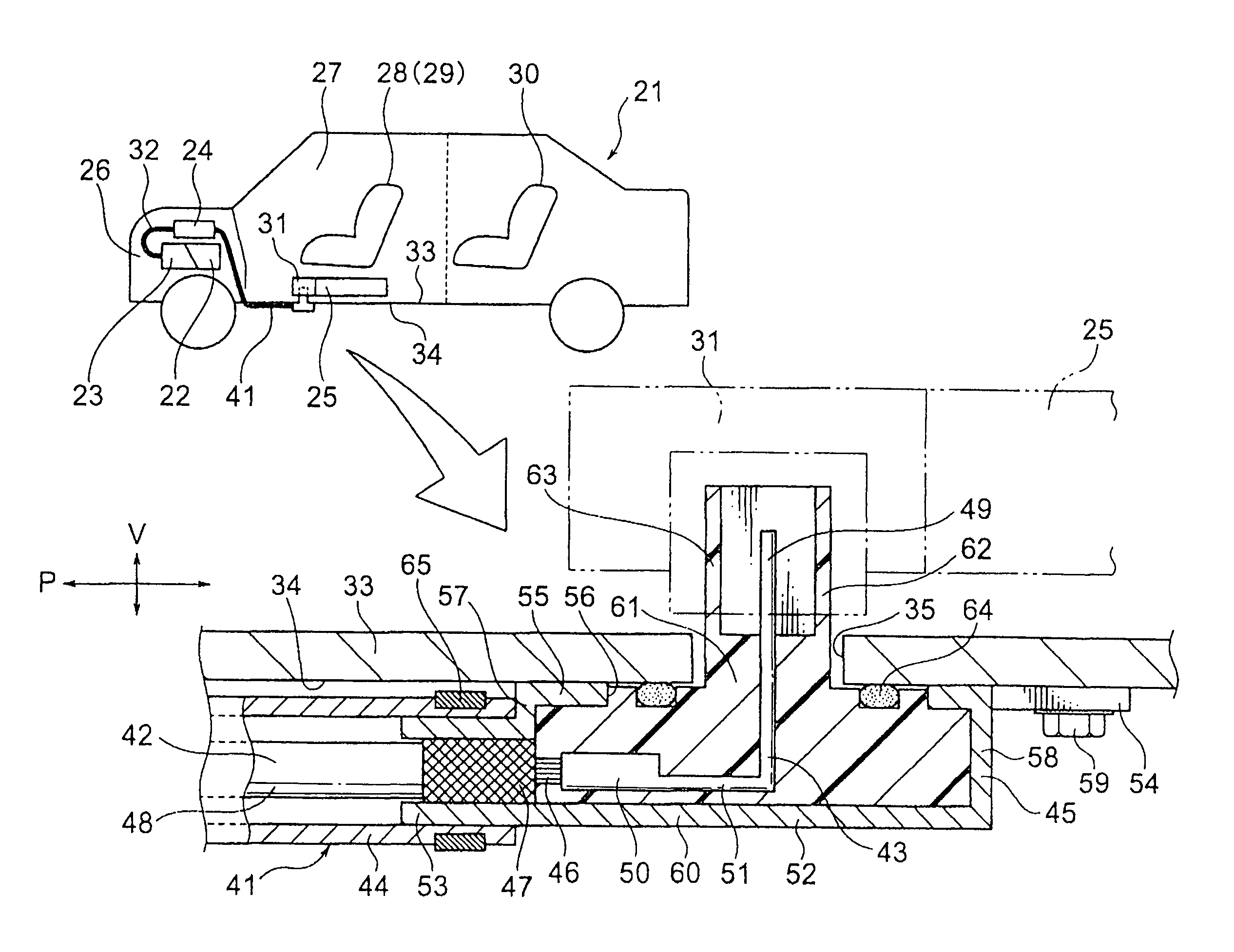
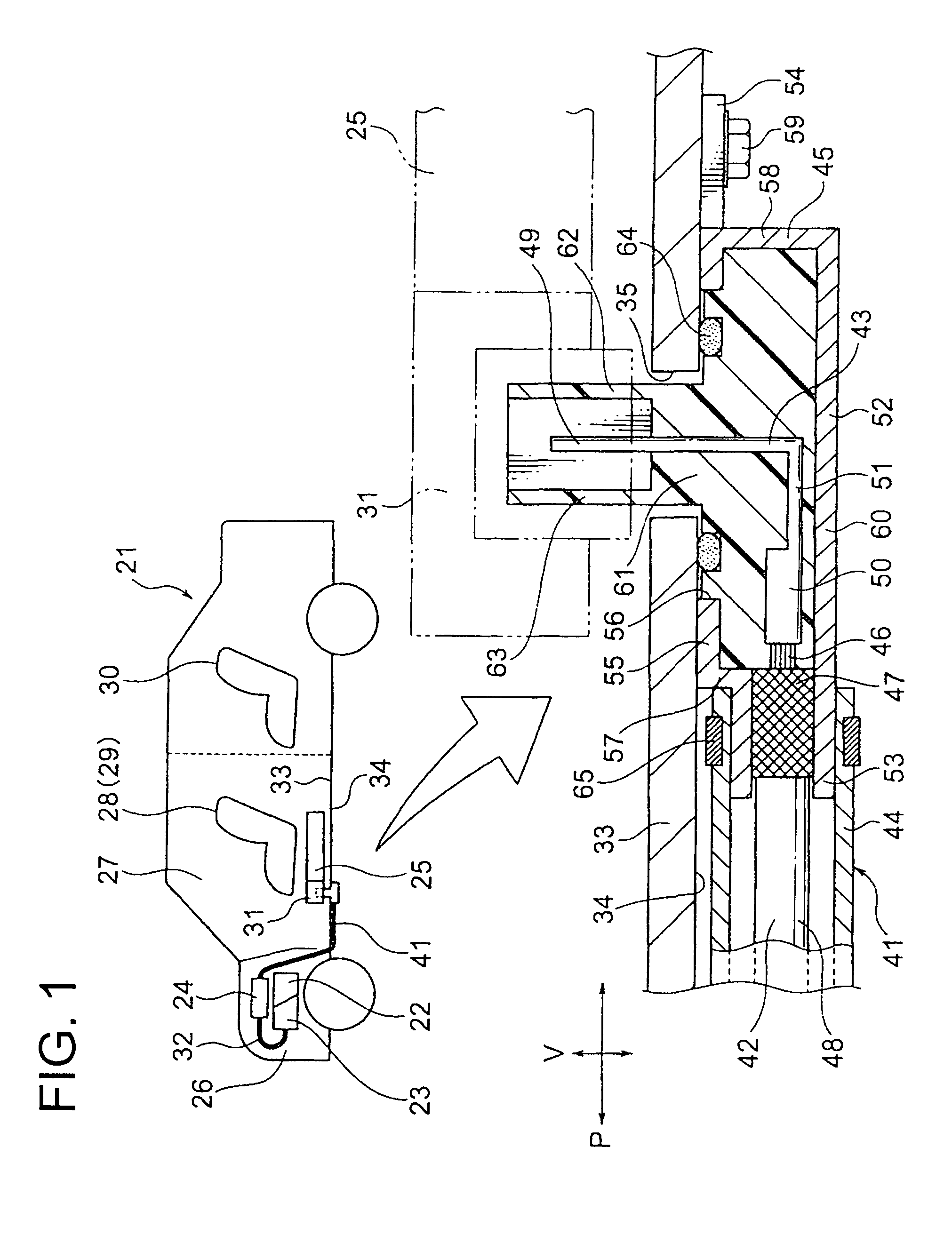
[0040]Hereinafter, a first embodiment of the present invention will be explained with reference to figures. FIG. 1 is a schematic view showing a wiring harness and a wiring structure of the wiring harness on a vehicle according to a first embodiment of the present invention, and a partially enlarged view of the same.

[0041]The wiring harness of this embodiment is used in a hybrid vehicle or an electric vehicle. Hereinafter, the wiring harness is used in the hybrid vehicle. (When the wiring harness is used in the electric vehicle, the basic structure and effect are the same as the hybrid vehicle. Incidentally, the present invention can be used not only in the hybrid vehicle and the electric vehicle, but also in a normal vehicle.)

[0042]In FIG. 1, the reference sign 21 indicates the hybrid vehicle. The hybrid vehicle 21 is driven by a combination of an engine 22 and a motor 23. An electric power is supplied to the motor 23 via an inverter 24 from a battery 25 (battery pack). In this emb...

second embodiment

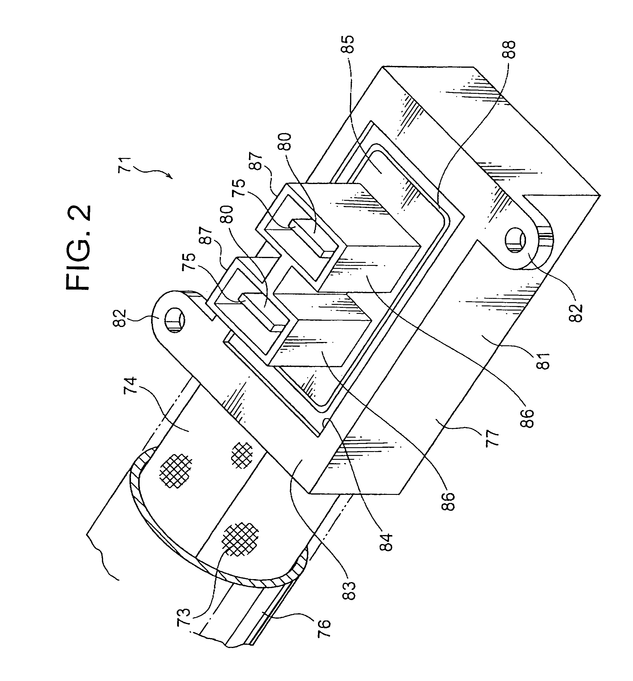
[0073]Hereinafter, a second embodiment of the present invention will be explained with reference to figures. FIG. 2 is a perspective view showing a terminal of the wiring harness according to a second embodiment of the present invention. FIG. 3 is a sectional view showing the high voltage cable of FIG. 2 and a wire protecting member. A wiring harness 71 explained below can be arranged on the hybrid vehicle 21 (see FIG. 1) instead of the wiring harness 41 according to the first embodiment.

[0074]In FIGS. 2 and 3, the wiring harness 71 is arranged from the engine room 26 shown in FIG. 1 to the underfloor 34. The wiring harness 71 is characterized in particular by arranging at the underfloor 34. The wiring harness 71 includes: a harness main body 74 having two high voltage cables 72 and shielding member 73; two connecting members 75 provided at one end of the harness main body 74 and electrically connecting the junction block 31 (see FIG. 1); a wire protecting member 76 for inserting an...


PUM

PropertyMeasurementUnit
voltageaaaaaaaaaa
thickaaaaaaaaaa
lengthaaaaaaaaaa

Abstract

A wiring arrangement of a wiring harness 41 at an underfloor 34 is finished by arranging a connecting member 43 to a position of a through-hole 35, by extending a sheath 48 on the underfloor 34 parallel to the underfloor 34 while the sheath 48 is received in a wire protect member 44, and by fixing a terminal fixing member 45 and the wire protecting member 44 to the underfloor 34. After such a wiring arrangement, the wiring harness 41 is electrically connected to a junction block 31 around the through-hole 35 by mounting a battery 25 or the like.

Description

CROSS REFERENCE TO RELATED APPLICATIONS[0001]This application is on the basis of Japanese Patent Application No. 2009-277766, the contents of which are hereby incorporated by reference.BACKGROUND OF THE INVENTION[0002]1. Field of the Invention[0003]The present invention relates to a wiring harness arranged on an underfloor at a ground side of a floor panel of a vehicle, and to a wiring structure of the wiring harness.[0004]2. Description of the Related Art[0005]A later-described Patent Document 1 discloses a wiring structure of a wiring harness used in a hybrid vehicle or an electric vehicle. Hereinafter an embodiment of the conventional wiring harness will be explained with reference to FIG. 4.[0006]In FIG. 4, a hybrid vehicle 1 includes a cabin 6 having a driver's seat 3, an assistant driver's seat 4, and a rear seat 5 behind an engine room 2. An engine 7, a motor, 8, and an inverter 9 are mounted on an engine room 2. A motor cable 10 connects the motor 8 with the inverter 9. One ...

Claims


Application Information

Patent Timeline
Patent Type & Authority Patents(United States)
IPC IPC(8): H01B7/30B60R16/02
CPCB60R16/0215B60L2210/10B60L2210/40Y02T10/70B60L50/40B60L50/16B60L58/21B60L50/66B60L50/64Y10T29/49117Y02T10/72Y02T10/7072
Inventor TOYAMA, EIICHIHASHIZAWA, SHIGEMI
Owner YAZAKI CORP
Why Eureka
Try Eureka