Light splitting assembly and imaging system

A spectroscopic component and imaging technology, applied in the field of imaging systems, can solve the problems of increasing equipment size, optical axis offset, optical performance degradation, etc., and achieve the effect of facilitating light weight and reducing size

Pending Publication Date: 2021-06-11
SUZHOU MICROCLEAR MEDICAL INSTR
View PDF1 Cites 0 Cited by
  • Summary
  • Abstract
  • Description
  • Claims
  • Application Information

AI Technical Summary

Problems solved by technology

[0004] (1) The 224 position of the dichroic mirror cannot arrange the internal fixation optical path, and the position of the internal fixation optical path needs to be moved back to the 204 position, which increases the size of the device to a certain extent
[0005] (2) For the transmitted light path, the dichroic mirror will cause the offset of the optical axis, and it has different offsets for light with different incident angles. This offset will bring about a decline in optical performance and affect large-field imaging especially serious
[0006] (3) The distance b

Method used


Image

  • Light splitting assembly and imaging system
  • Light splitting assembly and imaging system
  • Light splitting assembly and imaging system

Examples


Embodiment Construction

[0050] In order to make the technical solution of the present invention clearer, the technical solution of the present invention will be further described in detail below in conjunction with the accompanying drawings. It should be understood that the specific embodiments described here are only used to explain the present invention and not to limit the present invention. It should be noted that, in the case of no conflict, the embodiments in the present application and the features in the embodiments can be combined with each other.

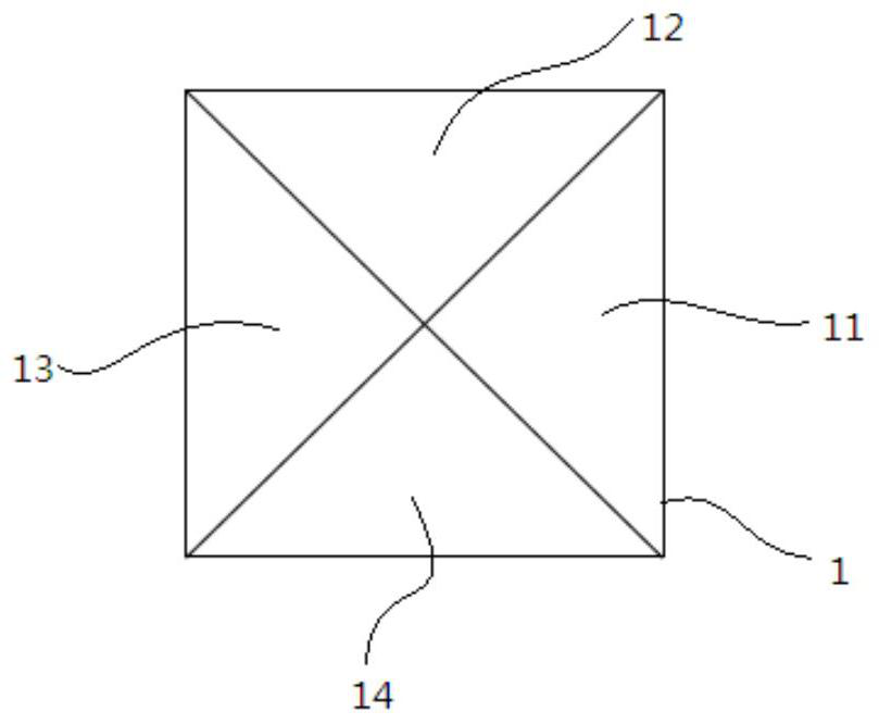
[0051] The first aspect of the present invention discloses a light splitting component, the light splitting component is a polyhedral structure, and at least two adjacent surfaces of the polyhedral structure are non-planar structures.

[0052] In the present application, the light-splitting component is a polyhedron structure, specifically, tetrahedron, pentahedron, hexahedron, heptahedron, octahedron, nonahedron, decahedron, undecahedron, dodeca...


PUM


Abstract

The invention relates to the field of imaging systems, in particular to a light splitting assembly and an imaging system. One aspect of the invention discloses the light splitting assembly, the light splitting assembly is of a polyhedral structure, and at least two adjacent surfaces in the polyhedral structure are of non-planar structures. According to the light splitting structure, light from different directions or different systems can be separated, the situation that the distance between a spectroscope and an eyepiece is too long or too small due to the fact that the spectroscope is arranged in a traditional light path system is avoided, the size of equipment is reduced, and light weight and miniaturization are facilitated.

Description

technical field [0001] The invention relates to the field of imaging systems, in particular to a spectroscopic component and an imaging system. Background technique [0002] Optical coherence tomography (OCT) is a three-dimensional tomographic imaging technology that can detect reflection or scattering signals at different depths in biological tissues, and has the advantages of non-contact, high resolution, and high speed. Since the invention of OCT technology, it has developed from the early time-domain OCT to the latest frequency-domain OCT, in which the frequency-domain system is divided into spectral domain OCT and frequency-sweeping OCT. The advantages in signal-to-noise ratio and imaging speed make frequency-domain OCT more widely used and recognized. [0003] Among them, in the prior art patent CN105011900A, it is disclosed that the LSO light and the OCT light 224 dichroic mirror position are combined, and then enter the human eye through the eyepiece 207, and after ...

Claims


Application Information

Patent Timeline
IPC IPC(8): A61B3/12A61B3/14
CPCA61B3/1225A61B3/14
Inventor 谢斌李超宏
Owner SUZHOU MICROCLEAR MEDICAL INSTR
Why Eureka
Try Eureka