Digitally controlled wide range pulse width modulator

a wide-range, modulator technology, applied in pulse automatic control, pulse generation by logic circuits, pulse techniques, etc., can solve the problem that the header and foot circuits currently known in the art do not provide a means for dynamically changing the duty cycle of pulse width modulators, and achieve high granularity dynamic voltage scaling (dvs), reduce reaction time, and high accuracy

Inactive Publication Date: 2015-04-14
UNIV OF SOUTH FLORIDA +1
View PDF7 Cites 2 Cited by
  • Summary
  • Abstract
  • Description
  • Claims
  • Application Information

AI Technical Summary

Benefits of technology

[0007]The present invention provides a digitally controlled pulse width modulator (PWM) which comprises a header circuit, a ring oscillator, and a duty cycle to voltage (DC2V) converter. The header circuit of the present invention controls the amount of current delivered to the PMOS transistors within the ring oscillator. Since the target specification is to vary the duty cycle between 50% and 90%, no footer circuitry is used to control the current of the NMOS transistors. Contrary to the conventional header circuits, where the header is connected to all of the inverters within the ring oscillator chain, the proposed header circuit is connected to every other inverter stage to improve the dynamic range of the duty cycle. This header circuit provides high granularity duty cycle control which has a step size of 2% of the period. Additionally, a DC2V converter, which is based on a frequency to voltage converter, is utilized to maintain the accuracy of the PWM under process, voltage, and temperature (PVT) variations. Under PVT variations, the maximum change in the duty cycle is less than 1.5% of the period.
[0013]As a result of the small on-chip area of the circuitry, fast control circuitry, high accuracy under PVT variations, and dynamic duty cycle control, the proposed pulse width modulator can dynamically change the duty cycle of the input switching signal for on-chip voltage regulators. The PWM circuitry will enable high granularity dynamic voltage scaling (DVS) at runtime and substantially reduce the reaction time from milliseconds to nanoseconds.

Problems solved by technology

However, the header and foot circuits currently known in the art do not provide a means for dynamically changing the duty cycle of the pulse width modulator.

Method used


Image

  • Digitally controlled wide range pulse width modulator
  • Digitally controlled wide range pulse width modulator
  • Digitally controlled wide range pulse width modulator

Examples


Embodiment Construction

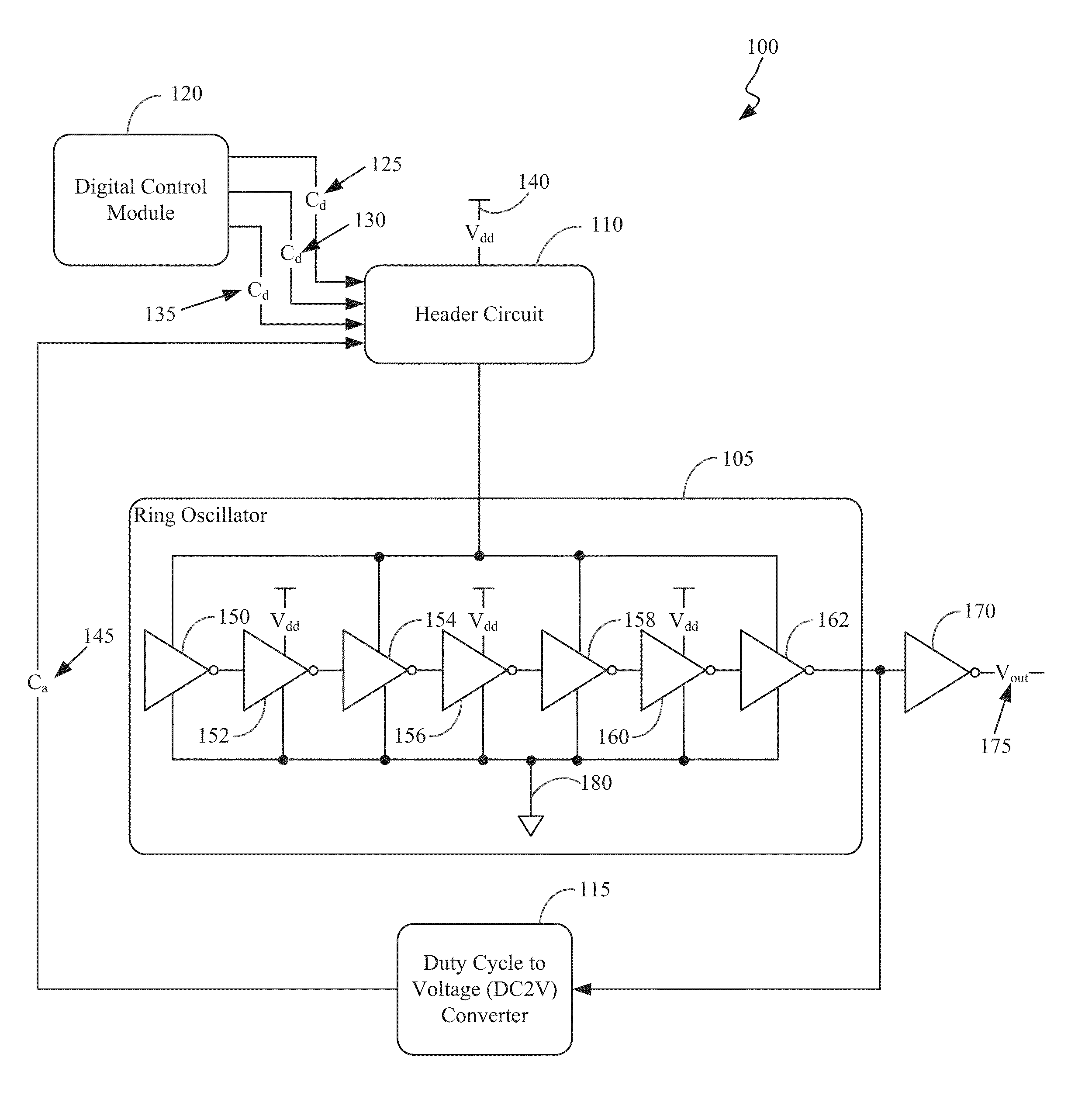
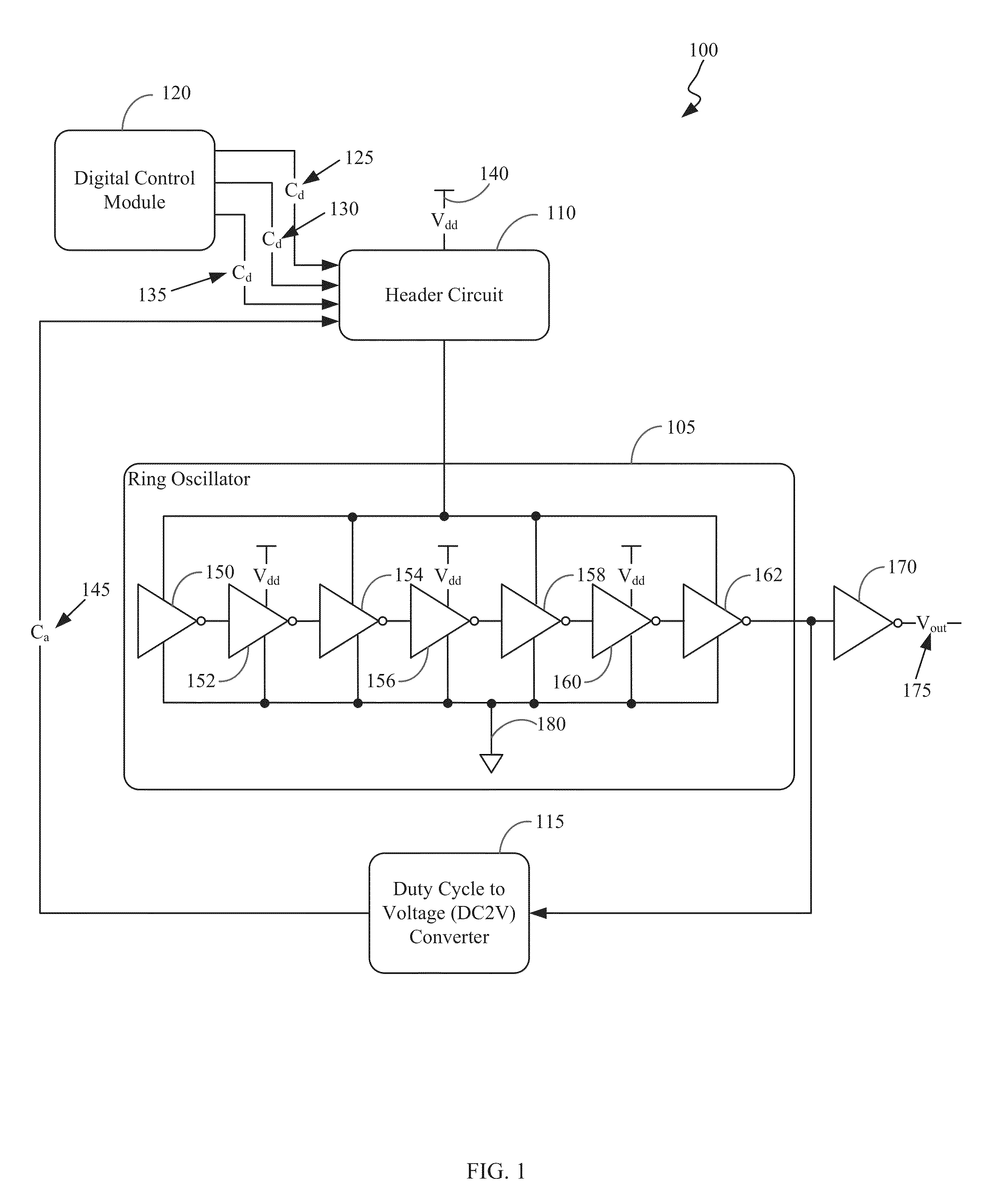
[0022]A diagram of a pulse width modulator 100 in accordance with an embodiment of the present invention is shown with reference to FIG. 1. In this particular embodiment, the pulse width modulator 100 utilizes a seven-stage ring oscillator 105. However, it is within the scope of the present invention to utilize a ring oscillator comprising a different number of stages.

[0023]In the embodiment of FIG. 1, the inverters are connected in a sequential loop to form the ring oscillator 105. In this embodiment, the first 150, third 154, fifth 158, and seventh 162 stages of the ring oscillator 105 are connected to the header circuit 110 and the inverters in the second 152, fourth 156 and sixth 160 stages of the ring oscillator 105 are connected directly to Vdd 140. Each of the inverter stages have a second input coupled to a ground node 180. In a ring oscillator, the inverters at every other stage generate the same logic function with a phase shift. By having the header circuit 110 connected ...


PUM


Abstract

The present invention provides a digitally controlled, current starved, pulse width modulator (PWM). In the PWM of the present invention, the amount of current from the voltage source to the ring oscillator is controlled by the proposed header circuit. By changing the header current, the pulse width of the switching signal generated at the output of the ring oscillator is dynamically controlled, where the duty cycle can vary between 50% and 90%. A duty cycle to voltage converter is used to ensure the accuracy of the system under process, voltage, and temperature (PVT) variations. The proposed pulse width modulator is appropriate for dynamic voltage scaling systems due to the small on-chip area and high accuracy under process, voltage, and temperature variations.

Description

CROSS-REFERENCE TO RELATED APPLICATIONS[0001]This application claims priority to U.S. Provisional Patent Application No. 61 / 750,072, entitled “DIGITALLY CONTROLLED WIDE RANGE PULSE WIDTH MODULATOR,” filed on Jan. 8, 2013, the contents of which are hereby incorporated by reference.STATEMENT OF GOVERNMENT INTEREST[0002]This invention was made with Government support under Grant No. CCF-0811317 awarded by the National Science Foundation (NSF). The Government has certain rights in the invention.BACKGROUND OF THE INVENTION[0003]Voltage controlled oscillators (VCOs) are widely used to generate a switching signal where some of the characteristics of the generated signal can also be controlled. Two types of VCOs are primarily used in high performance integrated circuits (ICs); inductor-capacitor (LC) oscillators and ring oscillators. LC oscillators can operate at very high frequencies and exhibit superior noise performance. Alternatively, ring oscillators occupy significantly smaller on-chi...

Claims


Application Information

Patent Timeline
Patent Type & Authority Patents(United States)
IPC IPC(8): H03K7/08
CPCH03K7/08
Inventor KOSE, SELCUKFRIEDMAN, EBY G.
Owner UNIV OF SOUTH FLORIDA
Why Eureka
Try Eureka