Navigation system including optical and non-optical sensors

a technology of optical and non-optical sensors and navigation systems, applied in the field of navigation systems, can solve the problems of many starts and stops, system may not accurately determine the position and/or orientation of the instrument and anatomy being tracked, and the accuracy and speed of optical navigation systems

Active Publication Date: 2015-04-14
STRYKER CORP
View PDF208 Cites 206 Cited by
  • Summary
  • Abstract
  • Description
  • Claims
  • Application Information

AI Technical Summary

Problems solved by technology

One of the limitations on accuracy and speed of optical navigation systems is that the system relies on the line-of-sight between the LEDs and the optical sensors of the camera unit.
When the line-of-sight is broken, the system may not accurately determine the position and / or orientation of the instrument and anatomy being tracked.
As a result, surgeries can encounter many starts and stops.
For instance, during control of robotically assisted cutting, when the line-of-sight is broken, the cutting tool must be disabled until the line-of-sight is regained.
This can cause significant delays and added cost to the procedure.
Another limitation on accuracy occurs when using active LEDs on the trackers.
However, because the LEDs are fired in sequence, there can be a considerable lag between measurements of any one LED.
Furthermore, this approximation does not take into account rotations of the trackers, resulting in further possible errors in position data for the trackers.

Method used


Image

  • Navigation system including optical and non-optical sensors
  • Navigation system including optical and non-optical sensors
  • Navigation system including optical and non-optical sensors

Examples


Embodiment Construction

I. Overview

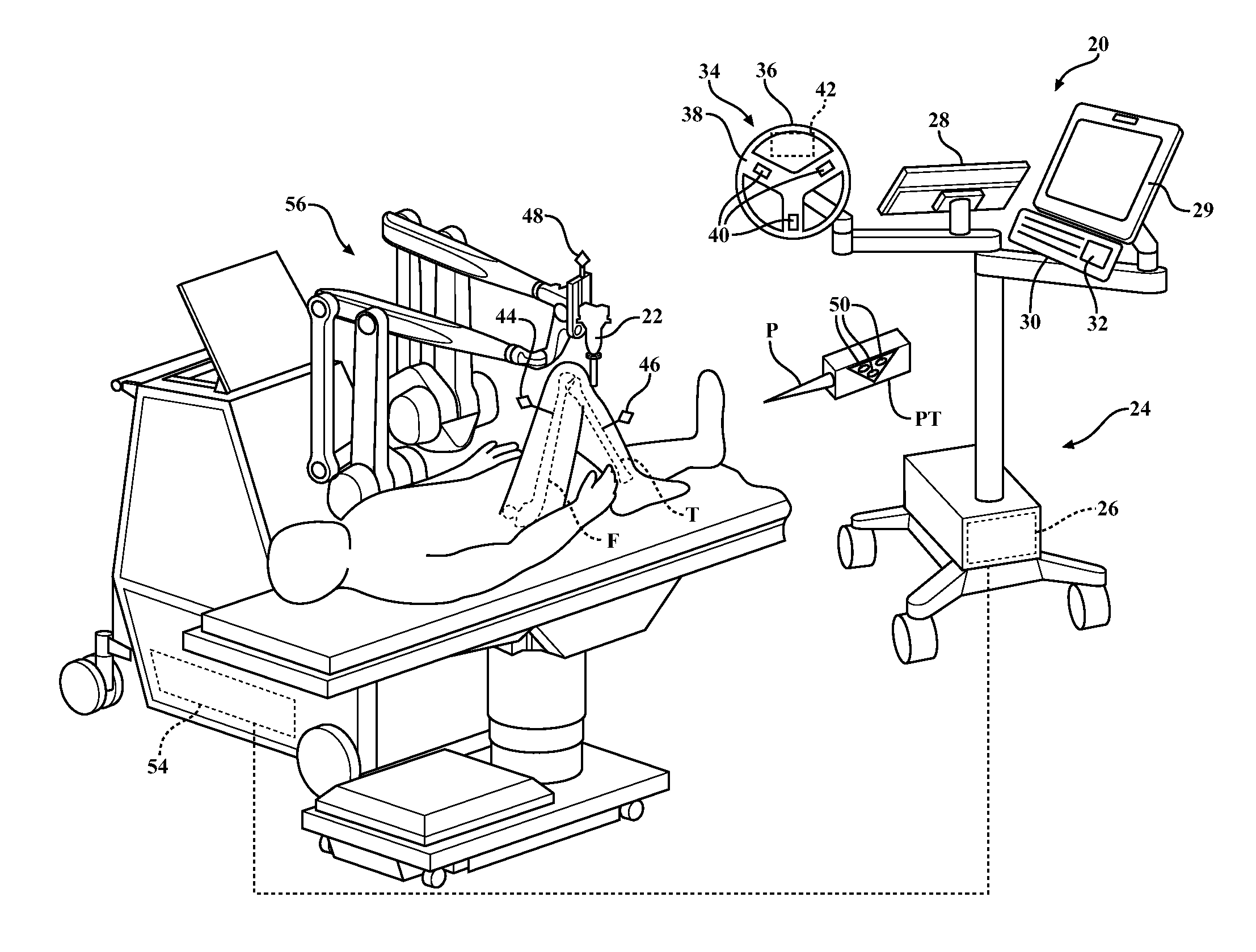
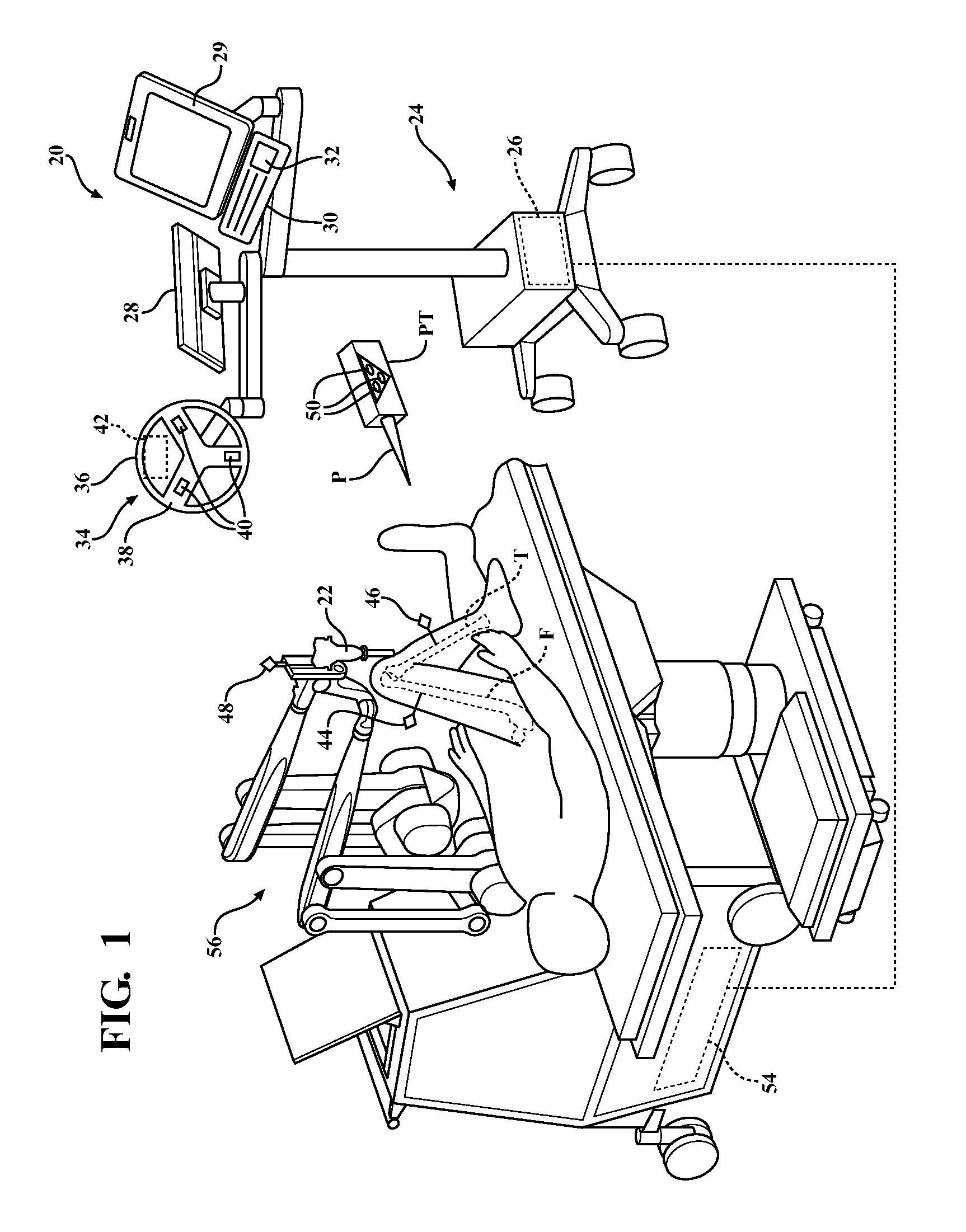
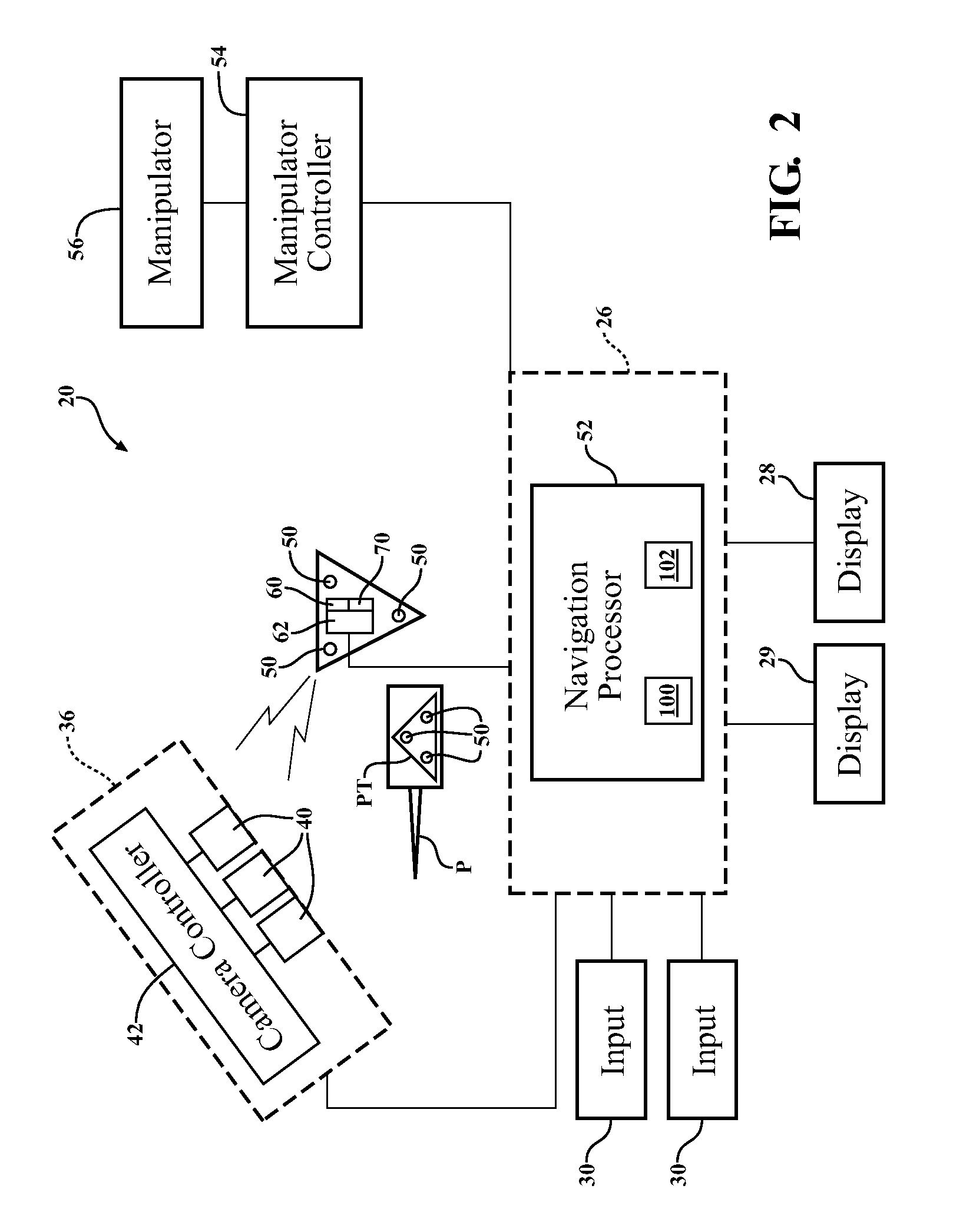
[0031]Referring to FIG. 1 a surgical navigation system 20 is illustrated. System 20 is shown in a surgical setting such as an operating room of a medical facility. The navigation system 20 is set up to track movement of various objects in the operating room. Such objects include, for example, a surgical instrument 22, a femur F of a patient, and a tibia T of the patient. The navigation system 20 tracks these objects for purposes of displaying their relative positions and orientations to the surgeon and, in some cases, for purposes of controlling or constraining movement of the surgical instrument 22 relative to a predefined path or anatomical boundary.

[0032]The surgical navigation system 20 includes a computer cart assembly 24 that houses a navigation computer 26. A navigation interface is in operative communication with the navigation computer 26. The navigation interface includes a display 28 adapted to be situated outside of the sterile field and a display 29 adapted t...


PUM


Abstract

Systems and methods that utilize optical sensors and non-optical sensors to determine the position and / or orientation of objects. A navigation system includes an optical sensor for receiving optical signals from markers and a non-optical sensor, such as a gyroscope, for generating non-optical data. A navigation computer determines positions and / or orientations of objects based on optical and non-optical data.

Description

RELATED APPLICATIONS[0001]This application claims priority to and the benefit of U.S. Provisional Patent Application No. 61 / 705,804, filed on Sep. 26, 2012, the entire contents of which are hereby incorporated by reference.FIELD OF THE INVENTION[0002]The present invention relates generally to a navigation system that tracks objects in space by determining changes in the position and / or orientation of such objects over time. More specifically, the present invention relates to navigation systems that utilize optical sensors and non-optical sensors to determine the position and / or orientation of objects.BACKGROUND OF THE INVENTION[0003]Navigation systems assist users in precisely locating objects. For instance, navigation systems are used in industrial, aerospace, defense, and medical applications. In the medical field, navigation systems assist surgeons in precisely placing surgical instruments relative to a patient's anatomy.[0004]Surgeries in which navigation systems are used includ...

Claims


Application Information

Patent Timeline
Patent Type & Authority Patents(United States)
IPC IPC(8): A61B5/05A61B5/06A61B19/00
CPCA61B5/064A61B19/5244A61B19/54A61B19/2203Y10S901/47A61B2019/4894A61B2019/5248A61B2019/5255A61B2019/5483A61B2090/3983A61B2090/0818A61B2034/2048A61B2034/2055A61B2090/3945A61B90/39A61B34/20A61B34/30A61B2034/2053
Inventor WU, CHUNWU
Owner STRYKER CORP
Why Eureka
Try Eureka