Module for an aircraft

a module and aircraft technology, applied in the field of modules for aircraft, can solve the problems of poor access to belongings, inefficient turnaround time, and interference of passengers, and achieve the effect of reducing the total weight of the structure and the cost, facilitating exchange, and strengthening the primary aircraft structur

Active Publication Date: 2015-04-21
AIRBUS SAS +1
View PDF113 Cites 10 Cited by
  • Summary
  • Abstract
  • Description
  • Claims
  • Application Information

AI Technical Summary

Benefits of technology

[0011]The wording fuselage structure shall define for instance the fuselage skin, the aircraft frames, the aircraft stringers or the cabin related parts. The wording floor element shall define for instance the different floor levels inside an aircraft. With the present invention it is possible to provide more stability for the connection of the functional elements. In order to meet current safety standards for functional elements it is necessary to design the connections of functional elements in such a manner, that the functional elements are able to withstand loads of 16 g in each direction. By using common connection methods, great effords have to be accomplished to comply with these requirements. As a result the connecting systems are very heavy and huge constructions. With the present invention, a lighter connection can be provided. By connecting the functional elements not exclusively in the floor plane but also in another plane, for instance to a fuselage structure, the forces that affect the functional elements can be reduced, because for instance the loads induced by acceleration torque can be minimized.
[0035]According to a further exemplary embodiment of the present invention, the module comprises a plurality of frame devices. Therewith it is possible, for instance, to design a module having an upper frame device including a functional element, for instance, a stowage bin and lighting, and having a second frame device including seats. Thus, it is possible to replace each frame device individually without a connection between the first frame device and the second frame device. Therewith more flexibility can be provided.

Problems solved by technology

The opening of the stowage bins is typically above the aisle orthogonal to the longitudinal direction of the fuselage, so that the passengers interfere themselves.
This results in inefficient turnaround time and the poor access to the belongings during the flight.

Method used


Image

  • Module for an aircraft
  • Module for an aircraft
  • Module for an aircraft

Examples


Embodiment Construction

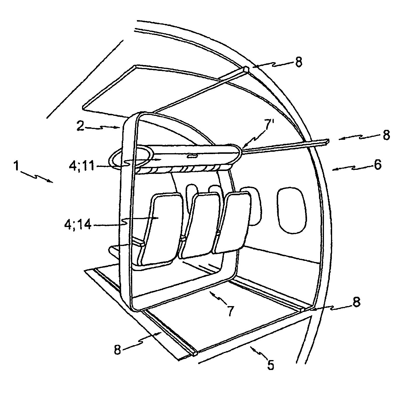
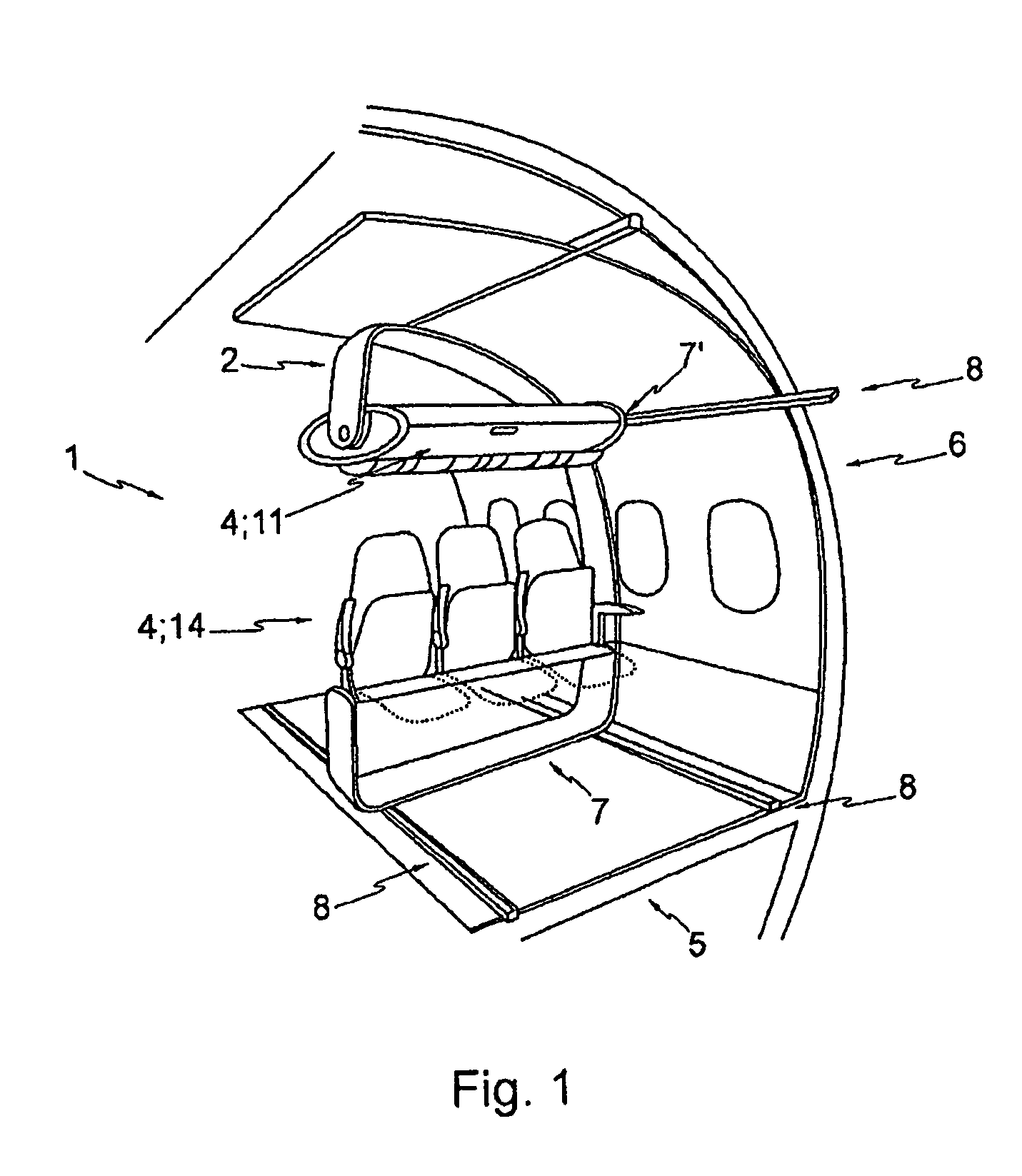
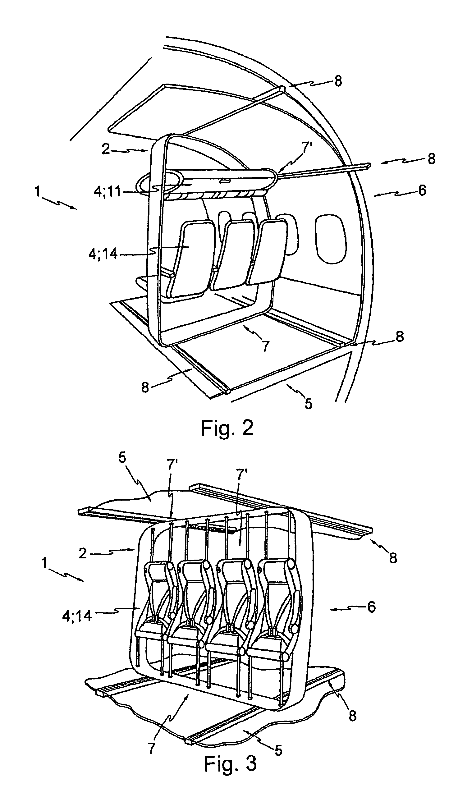
[0066]Similar or relating components in the several figures are provided with the same reference numerals. The view in the figures is schematic and not fully scaled.

[0067]FIG. 1 to 3 illustrate schematic views of exemplary embodiments of the present invention. A module for an aircraft is shown, wherein the aircraft having a fuselage structure 6 and a floor element 5. The floor element 5 defining a floor plane. The module comprises a frame device 2 wherein the frame device 2 is adapted for mounting a functional element 4. The frame device 2 is adapted for attachment to the floor element 5 of the aircraft at a first location 7 in the floor plane and wherein the frame device 2 is adapted for attachment to the fuselage structure 6 of the aircraft at a second location 7′. The second location 7′ is thereby not in the floor plane.

[0068]It is further illustrated a rail element 8 whereby the frame device 2 can be fixed relocatable respectively movable to the rail 8. By using as shown an airc...


PUM

PropertyMeasurementUnit
gravityaaaaaaaaaa
centre of gravityaaaaaaaaaa
distanceaaaaaaaaaa

Abstract

A module for an aircraft having a fuselage structure and a floor element defining a floor plane. The module includes a frame device adapted for mounting a functional element and the frame device is adapted for attachment to the floor element of the aircraft at a first location in the floor plane. The frame device is adapted for attachment to the fuselage structure of the aircraft at a second location, wherein the second location is not in the floor plane.

Description

REFERENCE TO RELATED APPLICATIONS[0001]This application claims the benefit of the filing date of European Patent Application No. 05 028 664.0 filed Dec. 29, 2005 and of U.S. Provisional Patent Application No. 60 / 754,745 filed Dec. 29, 2005, the disclosure of which applications is hereby incorporated herein by reference.TECHNICAL FIELD[0002]The present invention relates to a module, a system and a method for aircrafts, the use of a module in an aircraft and to an aircraft.BACKGROUND OF THE INVENTION[0003]Today's commercial aircraft cabins are designed to accommodate passengers and their luggage by providing several distinct and largely independent components. More precisely, the individual passenger cabin environment is made up of seats, for instance including underseat stowage, life vests, information placards, literature pouches, plus overhead stowage bins including passenger service units, for instance reading lights, air outlets, information signs, loudspeakers and supplemental o...

Claims


Application Information

Patent Timeline
Patent Type & Authority Patents(United States)
IPC IPC(8): B64D11/00B64D11/06
CPCB64D11/003B64D11/00B64D11/06B64D11/0696B64D2011/0046B64D11/0601B64D11/0611B64D11/0604Y02T50/46B64D11/06395Y02T50/40Y10T29/49826B64C1/18B64D11/0015B64D11/00154B64D11/0626B64D11/0627B64D11/0631B64D11/0639B64D11/0649B64D2011/0053
Inventor SAINT-JALMES, BRUNOREZAG, ANDREZANEBONI, JASONSCHUMACHER, MARKUSMUIN, ANDREWHAACK, CORDCARR, MICHAEL
Owner AIRBUS SAS
Why Eureka
Try Eureka