Mud pump

a pump and mud technology, applied in the field of pumps, can solve the problems of increasing the cost of drilling wells, and reducing the pressure of drilling mud, so as to achieve the effect of minimal friction

Active Publication Date: 2015-04-21
LESKO GERALD
View PDF6 Cites 46 Cited by
  • Summary
  • Abstract
  • Description
  • Claims
  • Application Information

AI Technical Summary

Benefits of technology

[0009]In one embodiment of the pump, the eccentric lobe can be rotatably disposed within a connecting rod having a substantially circular opening to receive the lobe at one end with the other end rotatably pinned to a slide configured to move in a horizontal and linear manner. In one embodiment, the slide can be slidably disposed within a pair of slide support plates that constrains the slide to move in a linearly and horizontal or side-to-side manner. In one embodiment, slide-bearing mechanisms can be disposed between the slide and the support plates so that the slide can move side-to-side with minimal friction. In a representative embodiment, the slide-bearing mechanism can further comprise means for adjusting a loading force on the slide-bearing mechanism against the slide so that the slide is further constrained to horizontal and linear movement.

Problems solved by technology

By coupling the pump module outputs to a common manifold, the pulsing of the pressure of the drilling mud can be reduced or smoothed out, this being a problem well known to those skilled in the art.
The disadvantage of this mechanical arrangement is the size and complexity of the components involved to provide a multi-module pump.
All this additional equipment and number of truckloads to deliver the equipment add cost to the drilling of the well.

Method used


Image

  • Mud pump
  • Mud pump
  • Mud pump

Examples


Embodiment Construction

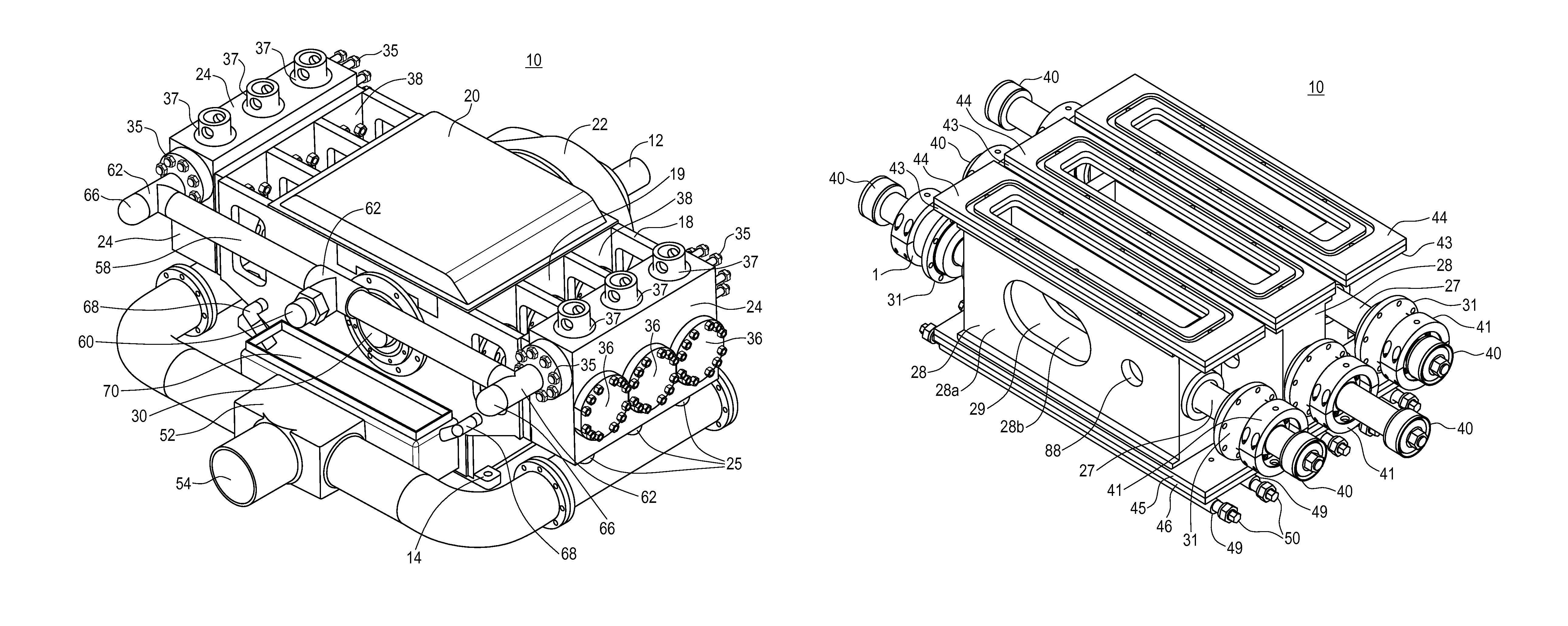
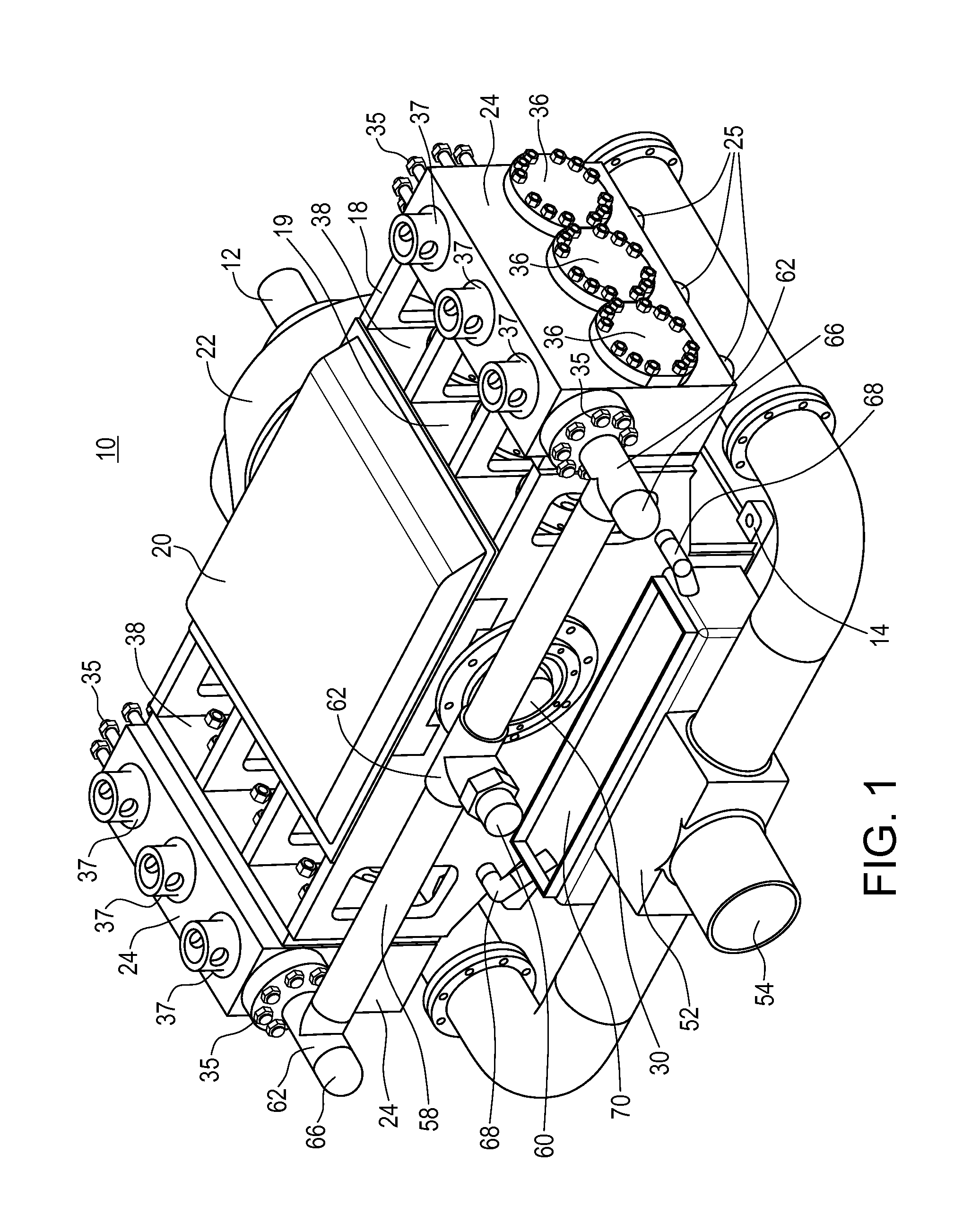
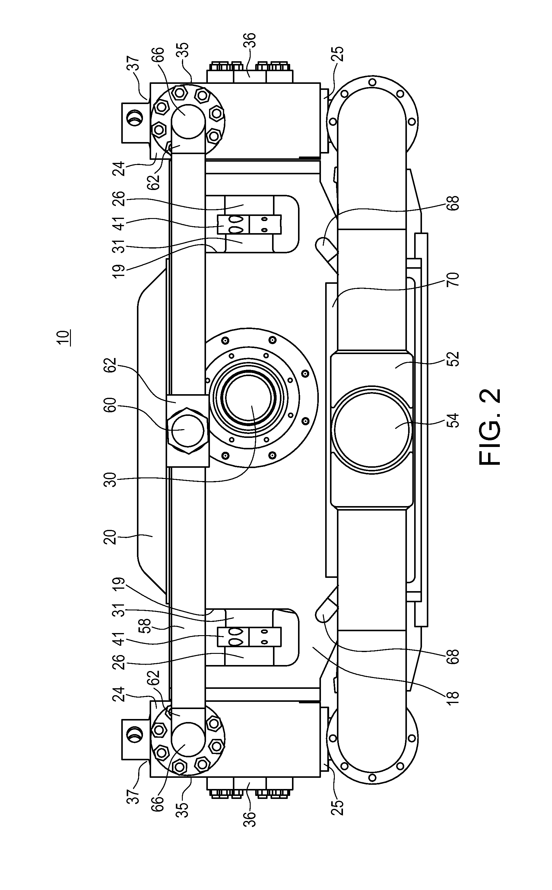
[0028]Referring to FIGS. 1 to 13, one embodiment of a mud pump is illustrated. In this embodiment, mud pump 10 can comprise lattice frame 18 and pump modules 24 mounted thereon. Frame 18 can further comprise mounting tabs 14 for attaching mud pump 10 to a platform, to a skid or to a pump house.

[0029]For the purposes of this specification, and as shown specifically in the figures, each pump module 24 can comprise inlet port 25, outlet port 35, top access port 37 and side access port 36. Pump module 24, as illustrated, can be any suitable pump module that is readily available to the mud pump industry and is well known to those skilled in the art. As shown in FIG. 1, pump module 24 is shown as a singular device having three pump units disposed therein. It is obvious to those skilled in the art that pump module 24 can comprise one or more pump units use in combination. Representative examples of pump module 24 are pump modules having an 800 horsepower rating as manufactured by Continent...


PUM


Abstract

A mud pump is provided that includes a pump shaft having substantially circular eccentric lobes. Each lobe is rotatably mounted in a connecting rod that, in turn, moves a slide in a horizontal and linearly manner. A piston rod is operatively couples a pump module to one or both sides of each slide frame and a pump module. As the pump shaft turns, each lobe causes the slide to move side to side. As the slide moves side to side, each piston rod operates a pump module whose outputs can be coupled to a common manifold.

Description

PRIORITY STATEMENT & CROSS-REFERENCE TO RELATED APPLICATIONS[0001]This application claims priority from U.S. Patent Application No. 61 / 345,858, entitled “Mud Pump” and filed on May 18, 2010, in the name of Gerald Lesko; which is hereby incorporated by reference for all purposes.TECHNICAL FIELD OF THE INVENTION[0002]The present disclosure is related to the field of pumps in general and, in particular, pumps used in pumping drilling mud or “mud pumps”.BACKGROUND OF THE INVENTION[0003]It is known to use pumps to provide drilling mud under pressure in the drilling of wells. Pressurized drilling mud is delivered down a hollow drill string as the well is being drilled to carry away cuttings up the annulus surrounding the drill string to ground level. Such drilling operations are well known to those skilled in the art.[0004]Prior art pumps can use a motor to turn a crankshaft or “pump shaft” to convert rotary motion to a reciprocating motion. The pump shaft moves a connecting rod coupled t...

Claims


Application Information

Patent Timeline
Patent Type & Authority Patents(United States)
IPC IPC(8): F04B53/14F04B9/04F04B15/02F04B53/16
CPCF04B15/02F04B53/146F04B9/042F04B53/16
Inventor LESKO, GERALD
Owner LESKO GERALD
Why Eureka
Try Eureka