
System and method for transmit and receive antenna patterns calibration for time division duplex (TDD) systems

Active Publication Date: 2015-04-21
MAGNOLIA BROADLAND INC
View PDF315 Cites 23 Cited by
  • Summary
  • Abstract
  • Description
  • Claims
  • Application Information

AI Technical Summary

Benefits of technology

The invention provides a calibration method for TDD systems that improves performance by effectively overcoming challenges in the art. The method calibrates transmit and receive antenna patterns to reduce or eliminate the need for feedback of channel state information during beam-forming and nulling operations. The calibration procedure is performed at a location with a line-of-sight view to the access point to minimize interference and mitigate fading. Overall, the method improves the efficiency and reliability of TDD systems.

Problems solved by technology

These feedbacks can consume some available bandwidth of the transmission in the opposite direction and reduce the data throughput.
The transmit path and receive path may thus experience very different gain / loss and delays behavior, due to the different components used in both paths.
Applying channel reciprocity without considering the different delay and gain / loss factors between the transmit / receive paths are therefore not valid and may not be accurate enough for the use by devices in TDD systems.
However, this calibration may be tedious and costly.
In addition, one important element that jeopardizes reciprocity is antennas, which project slightly different radiation patterns at up and down links, due to differences in the Voltage Standing Wave Ratio (VSWR) in both directions.
Antenna VSWR may not be practically calibrated in the factory, due to the cost and time of such procedures.
However, these methods may need an extra receive path with attenuator to calibrate transmit / receive (Tx / Rx) paths precisely on various power levels.
This may limit the use of the known methods for the devices that are not equipped with the extra receive path.

Method used


Image

  • System and method for transmit and receive antenna patterns calibration for time division duplex (TDD) systems
  • System and method for transmit and receive antenna patterns calibration for time division duplex (TDD) systems
  • System and method for transmit and receive antenna patterns calibration for time division duplex (TDD) systems

Examples


Embodiment Construction

[0039]In the following description, various aspects of the present invention will be described. For purposes of explanation, specific configurations and details are set forth in order to provide a thorough understanding of the present invention. However, it will also be apparent to one skilled in the art that the present invention may be practiced without the specific details presented herein. Furthermore, well known features may be omitted or simplified in order not to obscure the present invention.

[0040]Unless specifically stated otherwise, as apparent from the following discussions, it is appreciated that throughout the specification discussions utilizing terms such as “processing,”“computing,”“calculating,”“determining,” or the like, refer to the action and / or processes of a computer processor or computing system, or similar electronic computing device, that manipulates and / or transforms data represented as physical, such as electronic, quantities within the computing system's r...


PUM


Abstract

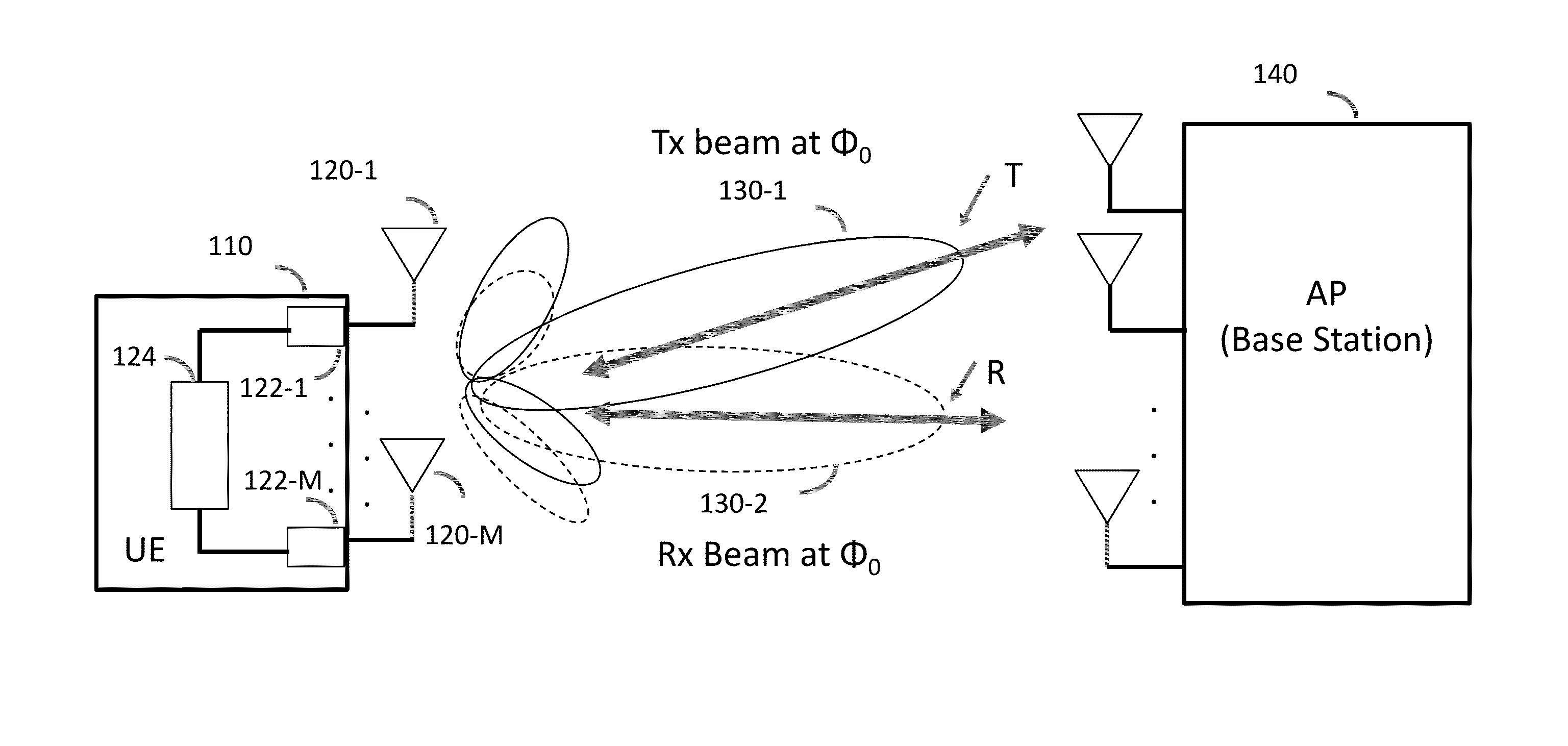
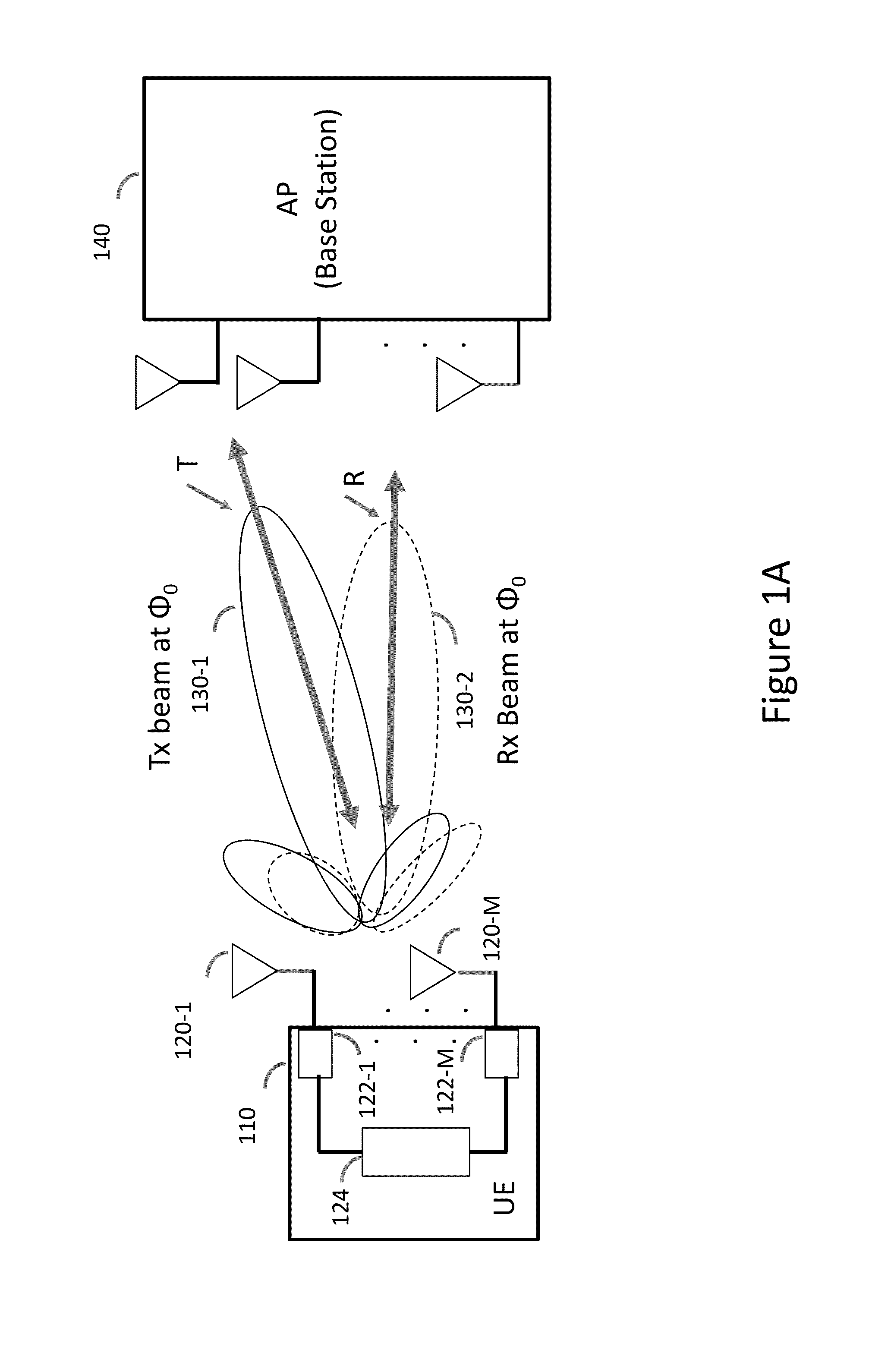
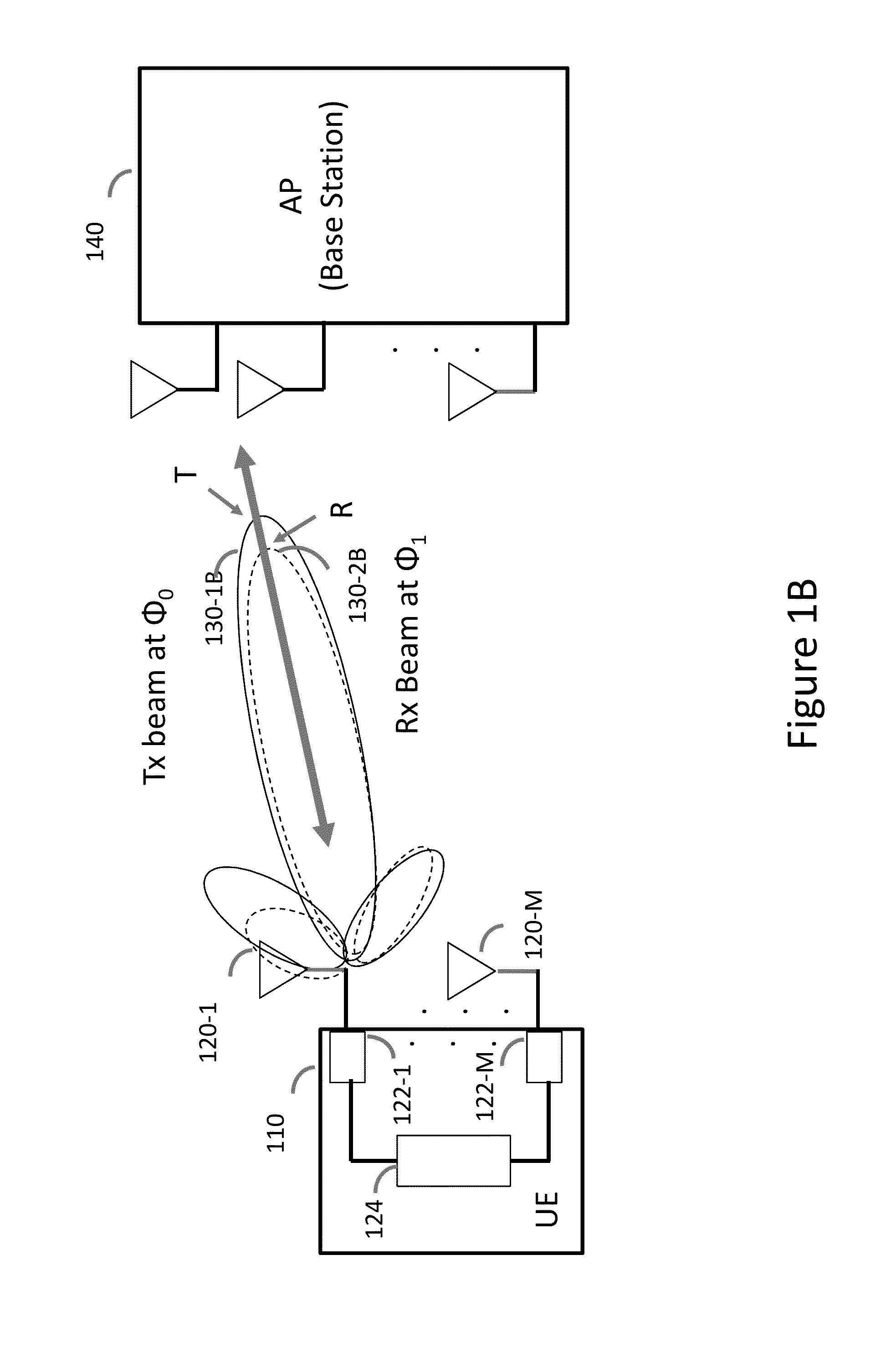
A method and system for applying a calibration procedure to match the peaks and nulls of the transmit and receive antenna patterns of a communication device are provided herein. The system may include: a plurality of antennas having tunable phases and configured for both transmitting and receiving; a plurality of radio circuits configured to transmit and receive via said antennas in a time division duplex (TDD) communication protocol; and a computer processor configured to calculate a weight setting difference between the transmit and the receive antenna pattern, wherein the antenna pattern is a peak-null pattern of the plurality of antennas operating together. The calibration value may enable the calibrated communication device to apply channel reciprocity to the beam-forming and / or nulling applications.

Description

CROSS REFERENCE TO RELATED APPLICATIONS[0001]This application claims the benefit of prior U.S. Provisional Application Ser. No. 61 / 909,135 filed 26 Nov. 2013 and prior U.S. Provisional Application Ser. No. 61 / 946,273 filed 28 Feb. 2014, which are incorporated herein by reference in their entirety.FIELD OF THE INVENTION[0002]The present invention relates generally to wireless communication systems, and more specifically, to such systems configured to calibrate transmit and receive antenna patterns thereof.BACKGROUND OF THE INVENTION[0003]Prior to setting forth a short discussion of the related art, it may be helpful to set forth definitions of certain terms that will be used hereinafter.[0004]The term “time division duplex” (TDD) as used herein, is defined for the wireless communication systems is referred to in general for systems using the same frequency spectrum for methods of communications in a time division manner (for example, Wi-Fi, and TDD-long term evolution (LTE) systems)....

Claims


Application Information

Patent Timeline
IPC IPC(8): H04J3/00H04L5/14H04W4/00H04B7/212H04B1/56H04B7/06
CPCH04B7/0665H04B1/56H04B7/0682H04B7/0413H04B17/12
Inventor WANG, SHERWIN J.HAREL, HAIMKLUDT, KENNETH
Owner MAGNOLIA BROADLAND INC
Learn More