Lower body muscle exercise device

a lower body, muscle technology, applied in the field of exercise devices, can solve the problems of difficulty in developing muscles, and limited muscle strength and development, and achieve the effects of improving muscle strength and growth, and reducing muscle mass

Inactive Publication Date: 2015-04-28
KOSICH MARK M
View PDF6 Cites 7 Cited by
  • Summary
  • Abstract
  • Description
  • Claims
  • Application Information

AI Technical Summary

Benefits of technology

[0016]The primary advantage of the invention is an exercise device to perform lower body muscle exercises, for example the quadruped hip extension exercise for the benefit of the gluteus muscle group, leg extensions for the benefit of the vastus medialis muscle or leg contractions for the benefit of the posterior thigh muscle group (hamstring muscles) including, for example, biceps femoris, semitendinosus, and semimembranosus muscles.
[0017]Another advantage of the invention is a non-mechanical device that provides simplicity, space savings and low cost yet has the advantage of mechanical equipment such as the ability to use weights and increase weight as needed to for strengthening and development of the lower body muscle groups.
[0018]A further advantage of the invention is a device that can hold substantial weight while allowing an operator to easily get into proper position to perform lower body muscle exercises.
[0019]And yet another advantage of the invention is a device that is utilized in strengthening and developing lower body muscle groups while minimizing discomfort and stress to the skeletal structure, muscles, tendons and ligaments of the body often associated with weight lifting using free weights and weight lifting machines.
[0020]Another advantage of the invention is to provide balance of the device with the center of gravity of secured weights in harmony with the anatomy of the body of the user.
[0021]Another advantage of the invention is the capability to adjust length or height of key components to accommodate variation of body types of users.

Problems solved by technology

While a reasonable degree of muscle tone can result, increase in muscle strength and growth may be limited.
Since the lower body has the largest muscle groups of the body, it is difficult to develop the muscles beyond the toning stage and obtaining substantial muscle strength and development is limited unless adequate resistance can be achieved.
If they are to hold more weight that this, the ankle weight becomes very difficult to hold in place on the ankle and lower leg area.
If the ankle weight has too much weight, lifting the foot upward becomes difficult and cumbersome for the operator.
It is likely that an exhausted operator will allow the foot with weighted ankle to fall to the floor too suddenly.
With ankle weights, a degree of effectiveness is lost since the weight is attached to the lower leg area.
It is unlikely that the device can hold more weight than ankle weights.
Therefore, an unbalanced condition is likely to be felt by the user resulting in less than ideal control of the device when moving through a range of motion to perform an exercise.
When used for lower body muscle training, for example, the quadruped hip extension exercise, disadvantages of the prior art are similar to the disadvantages of ankle weights.
Further, the prior art is restricted to the use of a dedicated type of weight which ads cost to the device.
Materials and fabrication also contribute to high cost of such a device.
These weight lifting exercises can place stress on the spine and knees.
Lunges, step-ups and squats can place strain on knee joints.
Performing squats, lunges, leg press and dead lifts with substantial weight can place stress on the skeleton, muscles, tendons and ligaments which can lead to discomfort and damage to these structures.
It is difficult to design a machine that can move in a way that can accommodate all body types.
Therefore, a set range of motion can cause stress and discomfort if the skeleton, muscles, tendons and ligaments are forced to move in a manner that is less than ideal.
Other disadvantages of machines include complexity, forced range of motion, space requirement and high cost.

Method used


Image

  • Lower body muscle exercise device
  • Lower body muscle exercise device
  • Lower body muscle exercise device

Examples


Embodiment Construction

[0057]A detailed description of the invention is provided herein. It is to be understood, however, that the present invention may be embodied in various forms. Therefore, specific details disclosed herein are not to be interpreted as limiting, but rather as a basis for the claims and as a representative basis for teaching one skilled in the art to employ the present invention in virtually any appropriately detailed system, structure or manner.

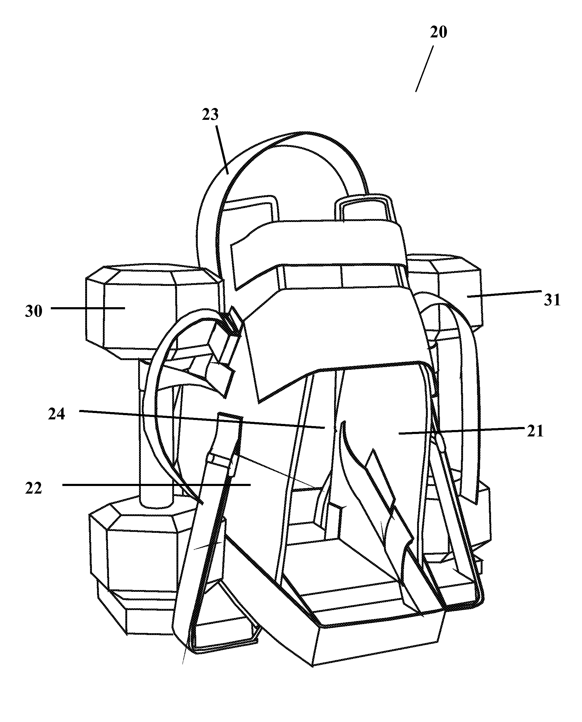
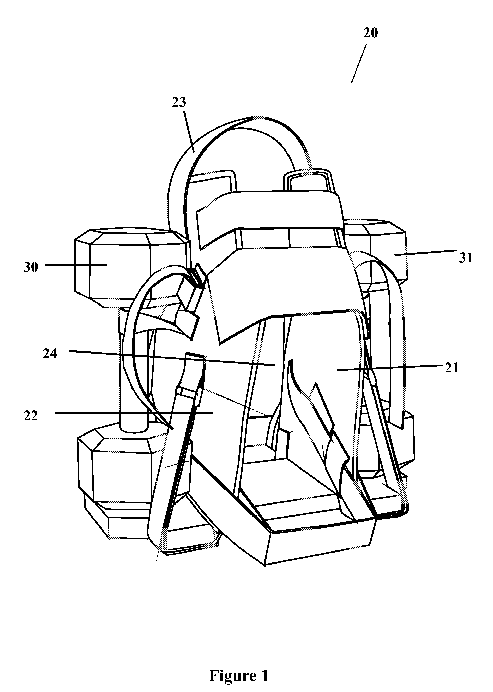
[0058]Turning first to FIG. 1, a front perspective view of the invention 20 shows the invention 20 which may be constructed of any of a wide range of materials including rigid material, flexible material or a combination of rigid and flexible materials. A plurality of parallel structures 21 and 22 are arranged in a vertical orientation to hold foot support 23 in an elevated position. Foot support 23 interconnects with vertical structures 21 and 22 and spans the gap 24 between them. Parallel structures 21 and 22 are positioned with adequate spac...


PUM


Abstract

An exercise device comprises a plurality of parallel structures having adequate length or height to insert the active foot of an operator and further comprises foot support means interconnecting the plurality of parallel structures, means to secure weights, and means to add or subtract weights. The device may be constructed of rigid or flexible materials or a combination of rigid and flexible materials. The device may also comprise means to minimize swinging motion. An operator, having an active leg and foot, inserts an active foot within the space between parallel structures, engages the foot support means with an active foot to perform lower body muscle exercises, for example, the quadruped hip extension exercise for the benefit of the gluteus muscle group, leg extensions for the benefit of the vastus medialis muscle or leg contractions for the benefit of the posterior thigh muscle group.

Description

CROSS REFERENCE TO RELATED APPLICATIONS[0001]U.S. Application No. 61 / 464,202; Filing Date: Mar. 1, 2011STATEMENT REGARDING FEDERALLY SPONSORED RESEARCH OF DEVELOPMENT[0002]Not ApplicableDESCRIPTION OF ATTACHED APPENDIX[0003]PTO / SB / 08a (01-10) Information Disclosure StatementBACKGROUND OF THE INVENTION[0004]This invention relates generally to the field of exercise equipment for weight resistance training for the primary benefit of the lower body muscles, for example, the quadruped hip extension exercise for the benefit of the gluteus muscle group, leg extensions for the benefit of the vastus medialis muscle and leg contractions or leg curls for the benefit of the posterior thigh muscle group (hamstring muscles) including, for example, biceps femoris, semitendinosus, and semimembranosus muscles. The invention relates more specifically to a non-mechanical device for weight resistance training that can hold substantial weight in a balanced manner, is free of the requirement to attach th...

Claims


Application Information

Patent Timeline
Patent Type & Authority Patents(United States)
IPC IPC(8): A63B23/04A63B21/065A63B21/075A63B21/00
CPCA63B23/04A63B21/065A63B21/075A63B21/143A63B21/1465A63B21/4015A63B21/4033
Inventor KOSICH, MARK M
Owner KOSICH MARK M
Why Eureka
Try Eureka