Alternating current rotating machine control device

a control device and rotating machine technology, applied in the direction of motor/generator/converter stopper, dynamo-electric converter control, multiple dynamo-motor starters, etc., can solve the problems of system instability and inability to automatically recover, and achieve the effect of strengthening the linkage and promoting the optimization of the whole system

Active Publication Date: 2015-04-28
FUJI ELECTRIC CO LTD
View PDF12 Cites 4 Cited by
  • Summary
  • Abstract
  • Description
  • Claims
  • Application Information

AI Technical Summary

Benefits of technology

[0019]According to the invention, when the plurality of power conversion devices are controlled to operate in concert, information of the plurality of alternating current rotating machine driving power conversion devices and other instruments is shared via a communication function, it is possible to strengthen the linkage, and thus possible to promote optimization of the whole system.
[0020]The heretofore described and other objects, characteristics, and advantages of the invention will be clarified by the attached drawings representing embodiments preferred as examples of the invention, and by the following related description.

Problems solved by technology

Because of this, in the event that communication from the master station becomes impossible for a reason such as a disconnection of the communication line 21 connecting the master station and slave stations or a failure of a communication control instrument, automatic recovery is not possible, and the system lacks stability.

Method used


Image

  • Alternating current rotating machine control device
  • Alternating current rotating machine control device
  • Alternating current rotating machine control device

Examples


embodiment 1

[0028](Embodiment 1)

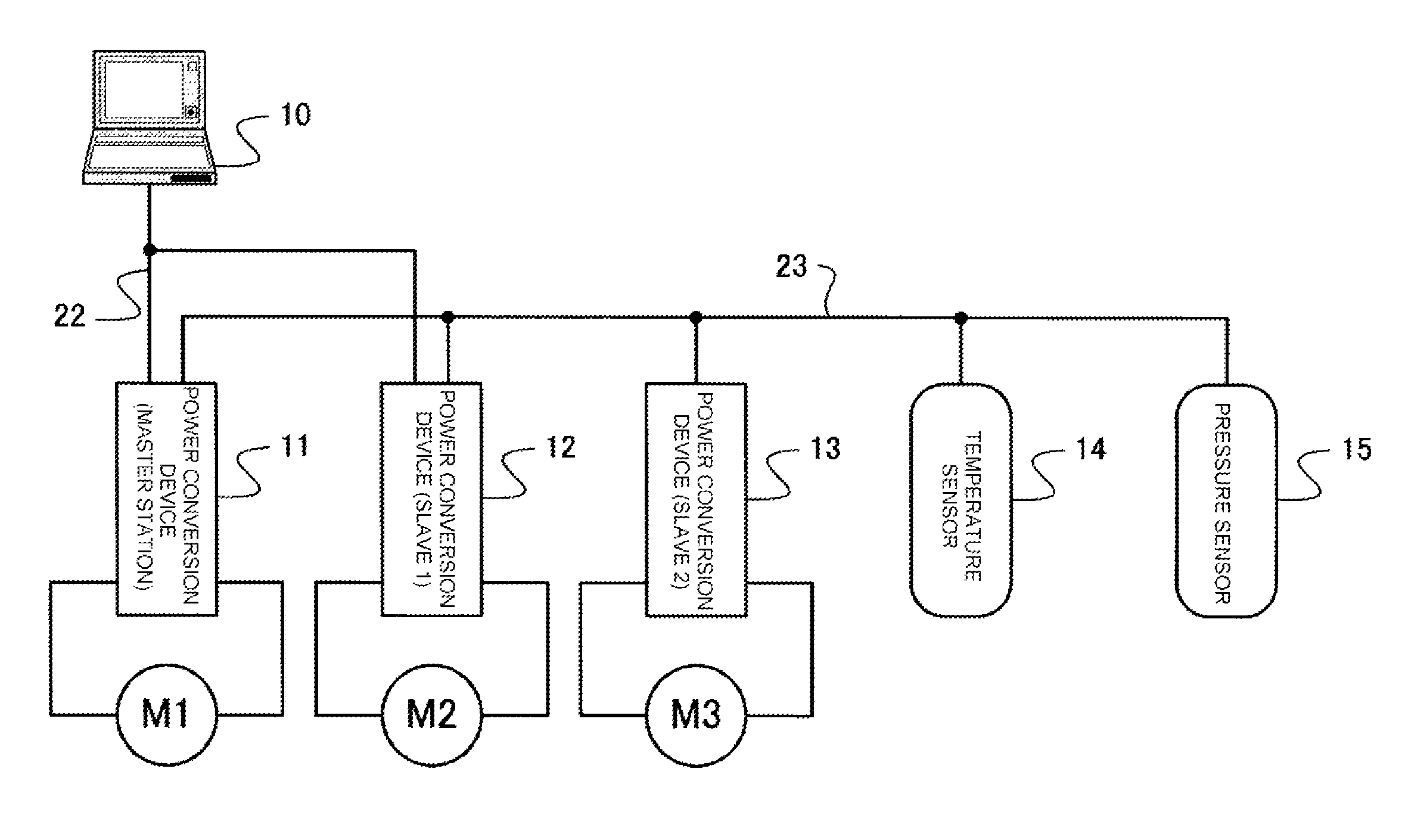
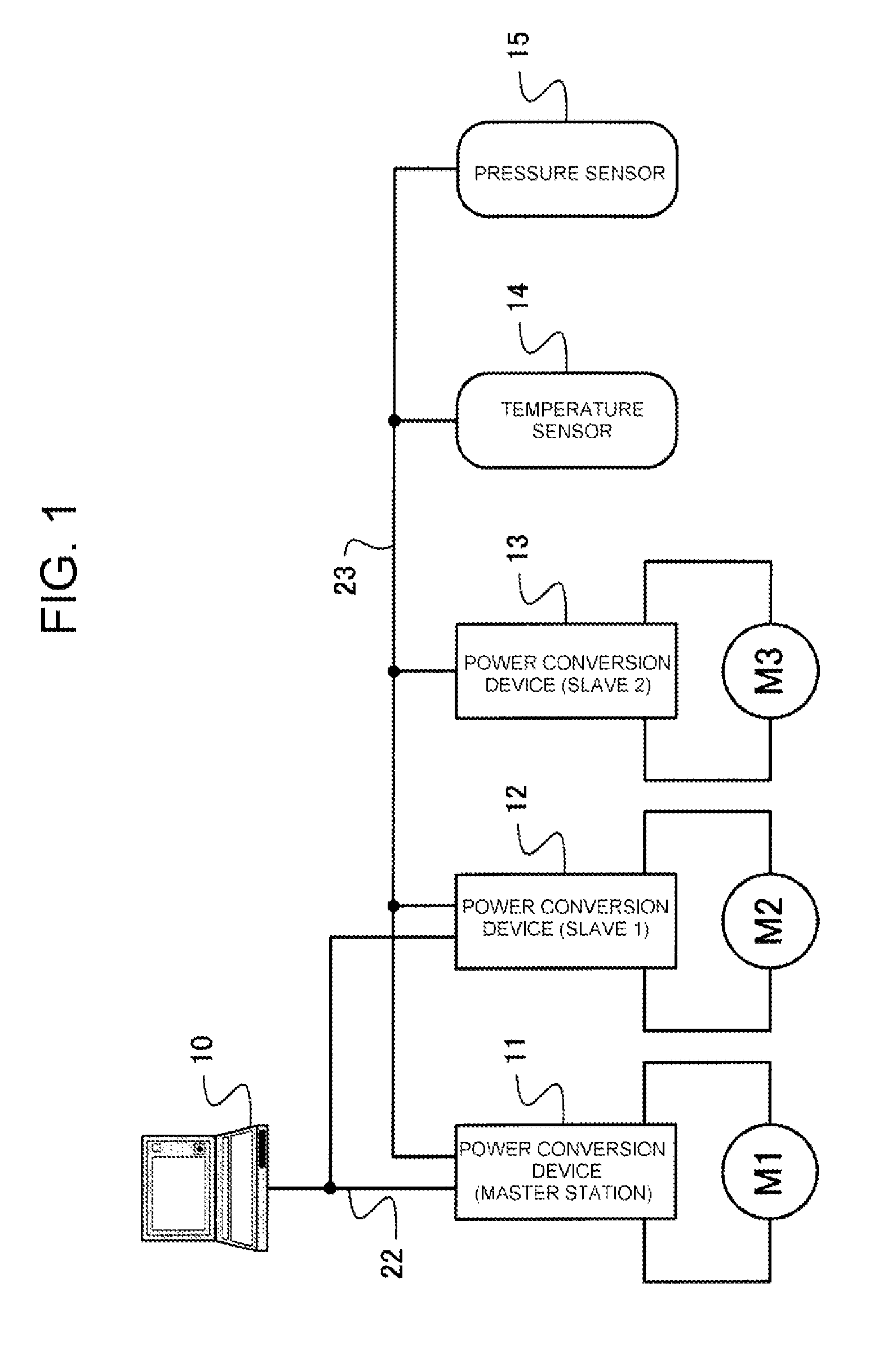
[0029]FIG. 1 is a block diagram showing a power conversion system according to Embodiment 1 of the invention.

[0030]The power conversion system is configured of a top level control device 10, a plurality of power conversion devices 11 to 13, accompanying information instruments, and the like. The top level control device 10 issues various kinds of command, such as a start / stop command or speed command, to the power conversion devices 11 to 13, or carries out a monitoring, or the like, of the status of the power conversion devices 11 to 13 or alternating current rotating machines M1 to M3. The power conversion devices 11 to 13 control the speed of the alternating current rotating machines M1 to M3 respectively. Herein, the accompanying information instruments are assumed to be various kinds of sensor instrument, such as a temperature sensor 14 and a pressure sensor 15, provided in a load such as a pump driven by the alternating current rotating machines M1 to M3 an...

embodiment 2

[0044](Embodiment 2)

[0045]FIG. 3 is a block diagram showing a power conversion system according to Embodiment 2 of the invention.

[0046]The power conversion system is configured of the plurality of power conversion devices 11 to 13 that control the speed of the alternating current rotating machines M1 to M3 respectively, accompanying information instruments, and the like. The power conversion devices 11 to 13 each having a different function, for example, the power conversion device 12 is equipped with a function detecting speed or position, or the like, while the power conversion device 13 is equipped with a clock function, or the like. Herein, the accompanying information instruments are assumed to be various kinds of sensor instrument, such as the temperature sensor 14 and pressure sensor 15, provided in a load such as a pump driven by the alternating current rotating machines M1 to M3 and the like. Also, the communication line 24 connects the three power conversion devices 11 to ...


PUM


Abstract

An alternating current rotating machine control device that shares information among power conversion devices and instruments. A power conversion system has a top level control device, a master station, multiple power conversion devices, instruments (such as a temperature sensor and a pressure sensor), and the like. The top level control device is connected to two of the power conversion devices by a first communication line. These power conversion devices have two or more communication functions, and are connected to a remaining power conversion device, a temperature sensor, and a pressure sensor by a second communication line.

Description

[0001]This application is the U.S. national stage of international application Ser. No. PCT / JP2012 / 051763, filed in Japan on Jan. 27, 2012, which claims priority from Japanese patent application Ser. No. 2011-031185, filed on Feb. 16, 2011, and herein incorporated by reference in its entirety.TECHNICAL FIELD[0002]The present invention relates to an alternating current rotating machine control device, and in particular, relates to an alternating current rotating machine control device wherein power conversion devices that drive a plurality of alternating current rotating machines at a predetermined speed are provided with a function of communicating with accompanying information instruments.BACKGROUND ART[0003]A power conversion system that operates a plurality of alternating current rotating machines with a plurality of inverter devices (power conversion devices) can generally be structured as a system including a master device, which forms a top level control device of the system, ...

Claims


Application Information

Patent Timeline
Patent Type & Authority Patents(United States)
IPC IPC(8): G06F15/16H02P5/74H04B3/52
CPCH04B3/52H02P5/74
Inventor ITOIGAWA, NOBUO
Owner FUJI ELECTRIC CO LTD
Why Eureka
Try Eureka