Bedmaker

a bedmaker and mattress technology, applied in the field of bedmakers, can solve the problems of employees missing work, placing on disability, and relatively heavy top mattresses

Active Publication Date: 2015-05-05
LEVITATION SCI
View PDF86 Cites 17 Cited by
  • Summary
  • Abstract
  • Description
  • Claims
  • Application Information

AI Technical Summary

Benefits of technology

[0011]Briefly, the present invention relates to a system and method for facilitating making beds of all sizes with one or more flat sheets by minimizing lifting of the mattress so that flat sheets and / or blankets can be tucked between the upper mattress and the box spring or platform without lifting the top mattress. As such, during an active mode, flat sheets and blankets can be tucked between a mattress and box spring or platform virtually effortlessly without the need to lift the top mattress. The present invention thus increases the efficiency of the housekeeping staff leaving more time for the housekeeping staff to attend to the rest of the room.

Problems solved by technology

Top mattresses are relatively heavy items.
Such sustained and repetitive lifting leads to employees developing back problems, resulting in employees missing work or, in severe cases, being placed on disability.
However, fitted sheets do not provide the “hospital corners” in the lower bed sheets that hospitals are known for.
For example, fitted sheets cost more than flat sheets.
Also, frequent washing of sheets in commercial facilities tends to wear out the elastic in fitted sheets.

Method used


Image

  • Bedmaker
  • Bedmaker
  • Bedmaker

Examples


first embodiment

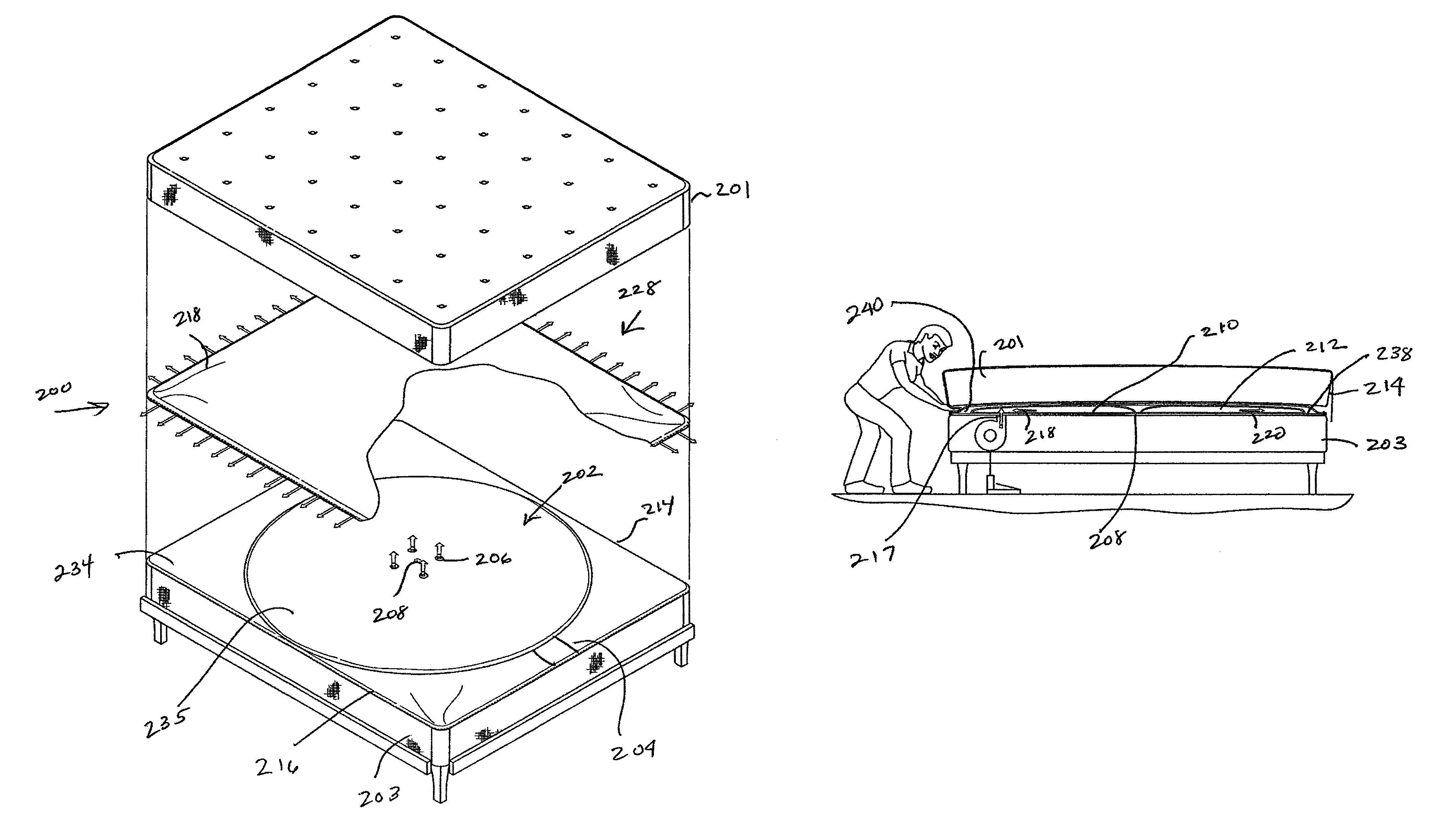
[0067]Referring first to FIGS. 30-37, the BedMaker™ device is illustrated. In this embodiment, the levitation device may be embedded in either the underside of the mattress or the top side of the box spring. As defined herein, “embedded” is defined to mean permanently attached, for example, by stitching, or removably attached using a fastener system, such as a zipper or a Velcro® fastening system to the surface of a box spring or mattress. Moreover, although the various embodiments, illustrated in FIGS. 30-43, show the air flow from the levitation device in an upward direction, the principles of the invention are applicable to embodiments in which the air flow from the levitation device is in a generally downward or upward direction.

[0068]Referring first to FIG. 30, a top mattress 201 and a box spring 203 are shown. The levitation device is generally identified with the reference numeral 200. The levitation device 200 includes an inflatable volume generally identified with the refer...

third embodiment

[0080]the invention is illustrated in FIGS. 40 and 41. This embodiment is an after-market embodiment, generally identified with the reference numeral 266 and includes two covers 268 and 270. Both covers 268 and 270 are formed as fitted sheets and are both installed either the upper mattress 201 with air blowing down, as shown in FIG. 40 or on the box spring 203 with air blowing up, as shown in FIG. 41. The covers 268 and 270 may be formed as discussed below in connection with FIG. 5, or as discussed above. In this embodiment, excess air naturally escapes between the covers 268 and 270, thus eliminating the need for sieves.

[0081]All of the embodiments discussed above with respect to the embodiments of the invention for facilitating making a bed operate in a similar manner and are explained with reference to FIGS. 35-37. Referring first to FIG. 35, portions of the mattress 201 around the edges lift when the air supply 250 (FIG. 43) is attached to the air inlet nozzle 204 (FIG. 30) and...


PUM

PropertyMeasurementUnit
angleaaaaaaaaaa
volumeaaaaaaaaaa
sizeaaaaaaaaaa

Abstract

Levitation devices are disclosed for use with beds. In one embodiment, the levitation device is configured to facilitate rotation of a mattress with respect to a box spring. In another embodiment, the levitation device is configured to facilitate making a bed which allows sheets and blankets to be tucked between the mattress and the box spring without the need to lift the mattress. In a third embodiment, the levitation device functions as a hybrid device and can be used for making a bed or rotating a mattress.

Description

CROSS REFERENCE TO RELATED APPLICATIONS[0001]This application is a continuation-in-part of U.S. patent application No. 13 / 078,385filed Mar. 1, 2011, now U.S Pat. No. 8,246,706, which, in turn, is a continuation of U.S. patent application Ser. No. 12 / 772,572filed May 3, 2010, now U.S. Pat. No. 8,006,331.BACKGROUND OF THE INVENTION[0002]1. Field of the Invention[0003]The present invention relates to a system and method for facilitating making beds of all sizes with one or more flat sheets by minimizing lifting of the mattress so that flat sheets and / or blankets can be tucked between the upper mattress and the box spring or platform without lifting the top mattress. 2. Description of the Prior Art.[0004]A conventional bed includes a box spring or bottom mattress or platform and a top mattress. Top mattresses are relatively heavy items. The weight of a mattress varies as a function of the coil core, the gauge of the coil and the type of material or foam material used. An average king si...

Claims


Application Information

Patent Timeline
Patent Type & Authority Patents(United States)
IPC IPC(8): A47C21/06A47C21/00
CPCA47C21/00A47C21/06Y10T29/49826A47C21/028
Inventor SCARLESKI, WILLIAM JOHN
Owner LEVITATION SCI
Why Eureka
Try Eureka