
Overvoltage protection method for backlight drive circuit of 2D/3D mode and backlight drive circuit using same

a backlight drive and overvoltage protection technology, applied in the direction of electric variable regulation, process and machine control, instruments, etc., can solve the problems of not being normally lit, not being able to drive, and not being able to meet the led string ,

Inactive Publication Date: 2015-05-05
TCL CHINA STAR OPTOELECTRONICS TECH CO LTD
View PDF7 Cites 4 Cited by
  • Summary
  • Abstract
  • Description
  • Claims
  • Application Information

AI Technical Summary

Benefits of technology

[0007]An object of the present invention is to provide an overvoltage protection method for backlight drive circuit of 2D / 3D mode, which uses a 2D / 3D signal source to control an electrical switch to close and open so as to control whether a first resistor is connected to the circuit for flow division so as to provides different overvoltage protection voltage levels for the 2D mode and the 3D mode to effect protection of components and extension of the lifespan of the components.
[0008]Another object of the present invention is to provide a backlight drive circuit, which provides different overvoltage protection voltage levels for a 2D mode and a 3D mode according to different levels of driving voltage of an LED (Light-Emitting Diode) string in the 2D mode and the 3D mode, so as to alleviate impact on components by over voltage when abnormality occurs in the 2D mode and thus extend the lifespan of the components.
[0030]The efficacy of the present invention is that the present invention provides an overvoltage protection method for backlight drive circuit of 2D / 3D mode, wherein by adding an electrical switch and a resistor and using a 2D / 3D signal source generated by a control board to control the electrical switch to conduct on or cut off, the resistor is disconnected in a 2D mode to lower down the overvoltage protection voltage level supplied in the 2D mode and the resistor is connected in a 3D mode to increase the overvoltage protection voltage level supplied in the 3D mode. According to the different levels of driving voltage that an LED string needs in the 2D mode and the 3D mode, different overvoltage protection voltage levels are supplied for the 2D mode and the 3D mode and the overvoltage protection voltage level supplied in the 2D mode is smaller than the overvoltage protection voltage level supplied in the 3D mode thereby alleviating impact on components by over voltage when abnormality occurs in the 2D mode and thus extending the lifespan of the components. The present invention also provides a backlight drive circuit, which supplies different overvoltage protection voltage levels for a 2D mode and a 3D mode according to the different levels of driving voltage that an LED string needs in the 2D mode and the 3D mode so as to alleviate impact on components by over voltage when abnormality occurs in the 2D mode and thus extend the lifespan of the components.

Problems solved by technology

On the other hand, if the voltage level for overvoltage protection is designed according to the required driving voltage for the LED string 100 in 2D mode, the driving voltage may not be sufficient for the LED string 100 in 3D mode, making it not normally lit.
When abnormality occurs in the operation in 2D mode, the output voltage is excessively high, which causes excessive instantaneous impact to the components of the backlight drive circuit, thereby shortening the lifespan of the components.

Method used


Image

  • Overvoltage protection method for backlight drive circuit of 2D/3D mode and backlight drive circuit using same
  • Overvoltage protection method for backlight drive circuit of 2D/3D mode and backlight drive circuit using same
  • Overvoltage protection method for backlight drive circuit of 2D/3D mode and backlight drive circuit using same

Examples


Embodiment Construction

[0036]To further expound the technical solution adopted in the present invention and the advantages thereof, a detailed description is given to a preferred embodiment of the present invention and the attached drawings.

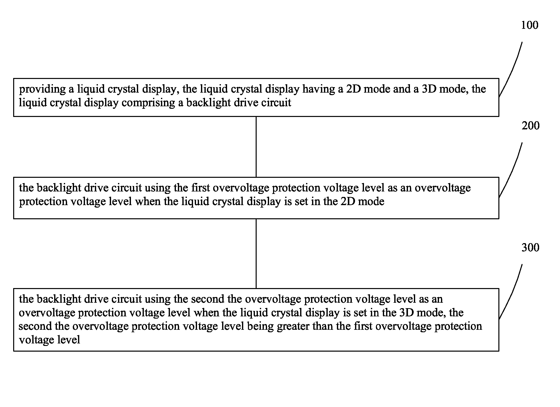
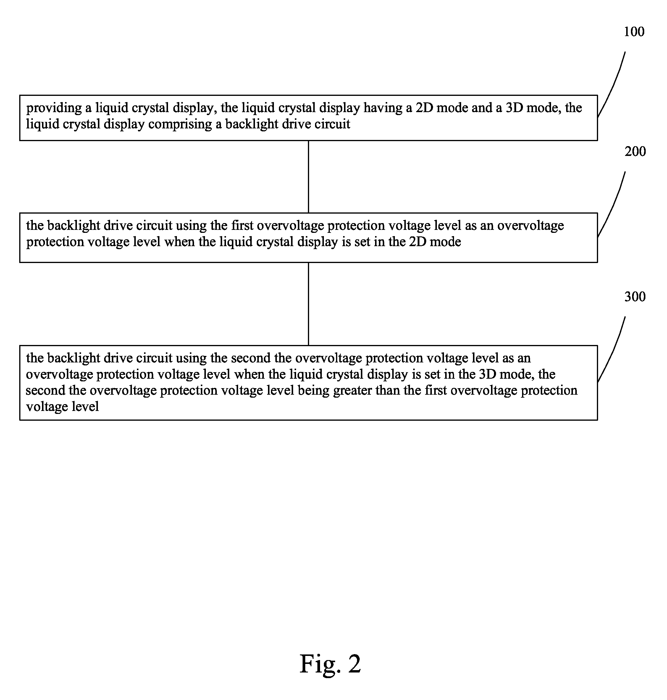
[0037]Referring to FIGS. 2 and 3, the present invention provides an overvoltage protection method for backlight drive circuit of 2D / 3D mode, which comprises the following steps:

[0038]Step 100: providing a liquid crystal display (not shown), the liquid crystal display having a 2D mode and a 3D mode, the liquid crystal display comprising a backlight drive circuit.

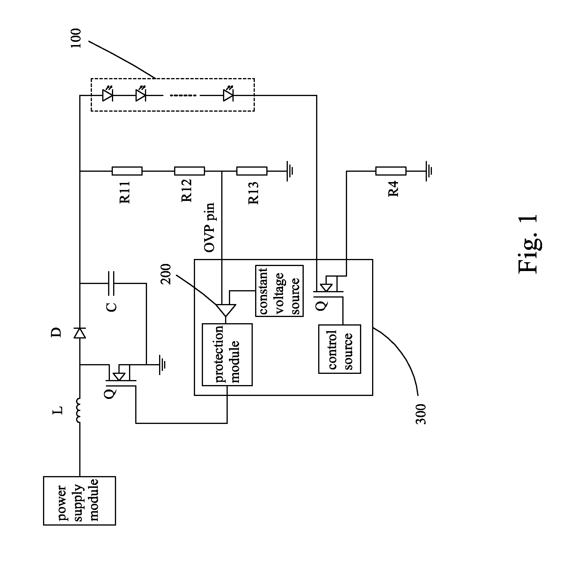
[0039]In the instant preferred embodiment, the backlight drive circuit comprises: a power supply module 2, an electrical inductor L, which has an end electrically connected to the power supply module 2, and a rectification module electrically connected to an opposite end of the electrical inductor L, a filter module electrically connected to an opposite end of the rectification module, a voltage division module ...


PUM


Abstract

The present invention provides an overvoltage protection method for backlight drive circuit of 2D / 3D mode and a backlight drive circuit using the method. The method includes: providing a liquid crystal display, the liquid crystal display having a 2D mode and a 3D mode, the liquid crystal display including a backlight drive circuit; the backlight drive circuit using the first overvoltage protection voltage level as an overvoltage protection voltage level when the liquid crystal display is set in the 2D mode; and the backlight drive circuit using the second the overvoltage protection voltage level as an overvoltage protection voltage level when the liquid crystal display is set in the 3D mode, the second the overvoltage protection voltage level being greater than the first overvoltage protection voltage level. Different overvoltage protection voltage levels are provided for the 2D and 3D modes so as to alleviate impact on components by over voltage.

Description

BACKGROUND OF THE INVENTION[0001]1. Field of the Invention[0002]The present invention relates to the field of liquid crystal display, and in particular to an LED (Light-Emitting Diode) backlight drive method and drive circuit of liquid crystal display.[0003]2. The Related Arts[0004]Liquid crystal displays (LCDs) have a variety of advantages, such as thin device body, low power consumption, and being free of radiation, and is thus widely used. Most of the LCDs that are currently available in the market are backlighting LCDs, which comprise a liquid crystal panel and a backlight module. The operative principle of the liquid crystal panel is that liquid crystal molecules are interposed between two parallel glass substrates and the liquid crystal molecules are controlled to change direction by application of electricity to the glass substrates in order to refract out light emitting from the backlight module for generating images. Since the liquid crystal panel itself does not emit light...

Claims


Application Information

Patent Timeline
Patent Type & Authority Patents(United States)
IPC IPC(8): G05F1/00H05B44/00
CPCH05B33/0887H05B33/0809Y02B20/341G09G3/003G09G3/342G09G2330/04Y02B20/30H05B45/10H05B47/24
Inventor ZHANG, HUAZHANG, XIANMING
Owner TCL CHINA STAR OPTOELECTRONICS TECH CO LTD
Learn More