Image processing apparatus and method for correcting deformation in a tomographic image
a tomographic image and image processing technology, applied in the field of image processing apparatus and method, can solve problems such as volume image deformation, and achieve the effect of accurately correcting volume image deformation
- Summary
- Abstract
- Description
- Claims
- Application Information
AI Technical Summary
Benefits of technology
Problems solved by technology
Method used
Image
Examples
first embodiment
[0034]Hereinafter, referring to the attached drawings, a first embodiment of the present invention is described. Note that, the image processing apparatus according to this embodiment estimates a shape model from a plurality of tomographic images obtained by photographing spatially separated points at the same time when photographing a volume image with a plurality of measuring light beams. Then, the shape model is used for alignment of neighboring tomographic images so that volume image deformation is corrected. Hereinafter, an image processing system including the image processing apparatus according to this embodiment is described in detail.
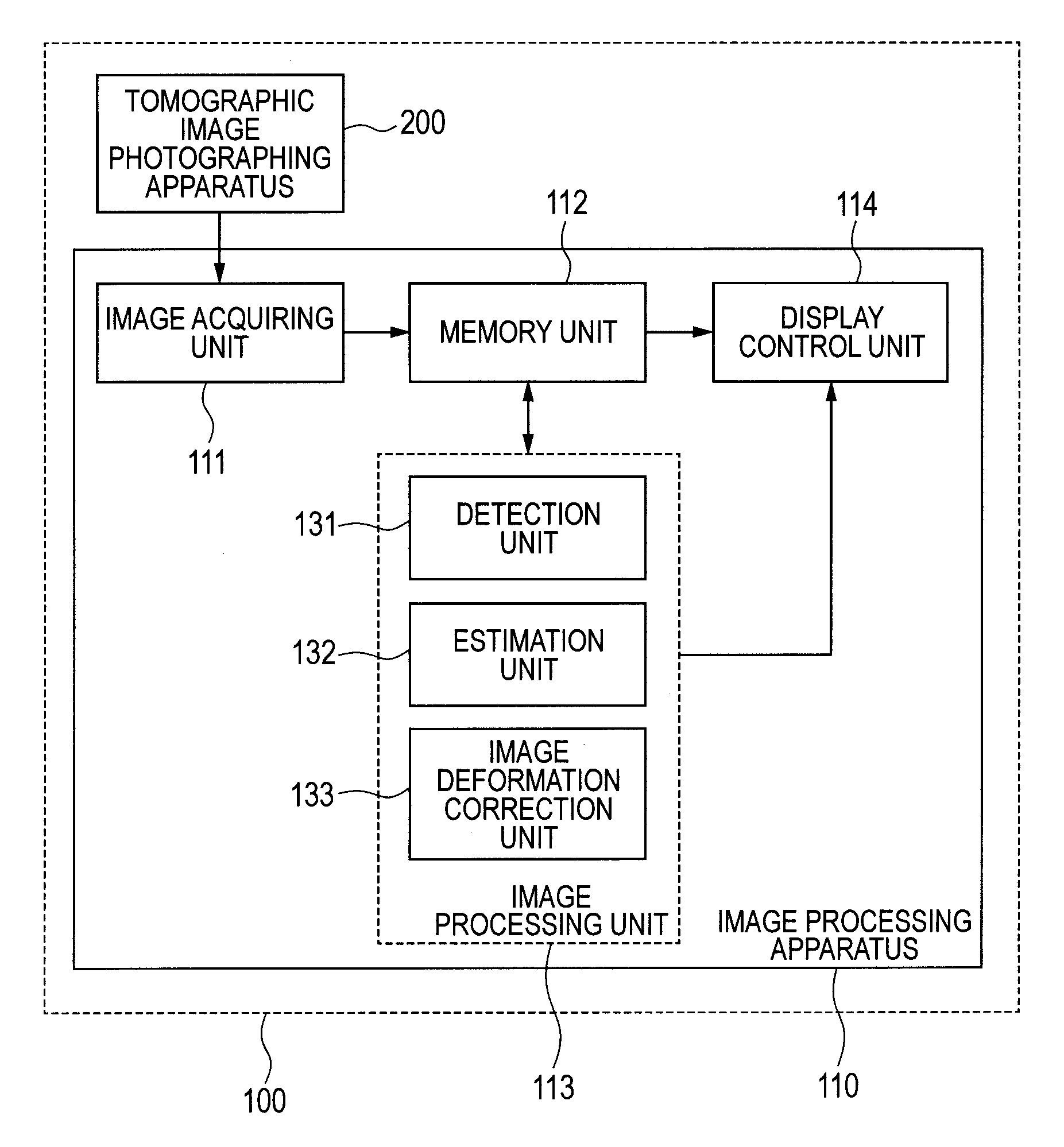
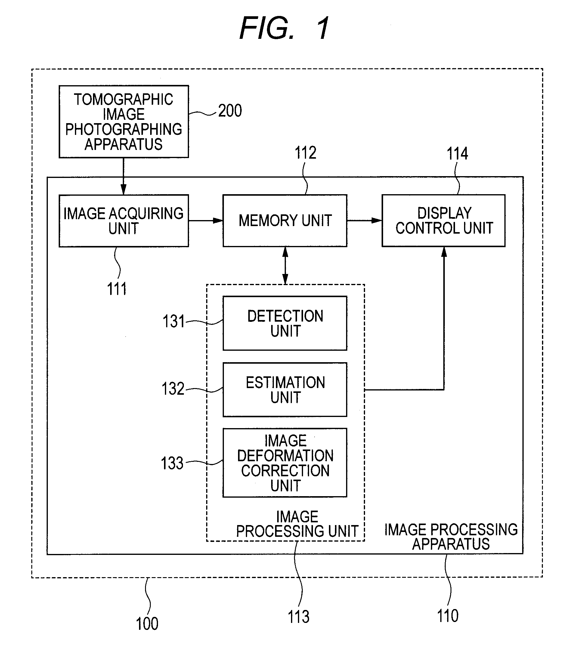
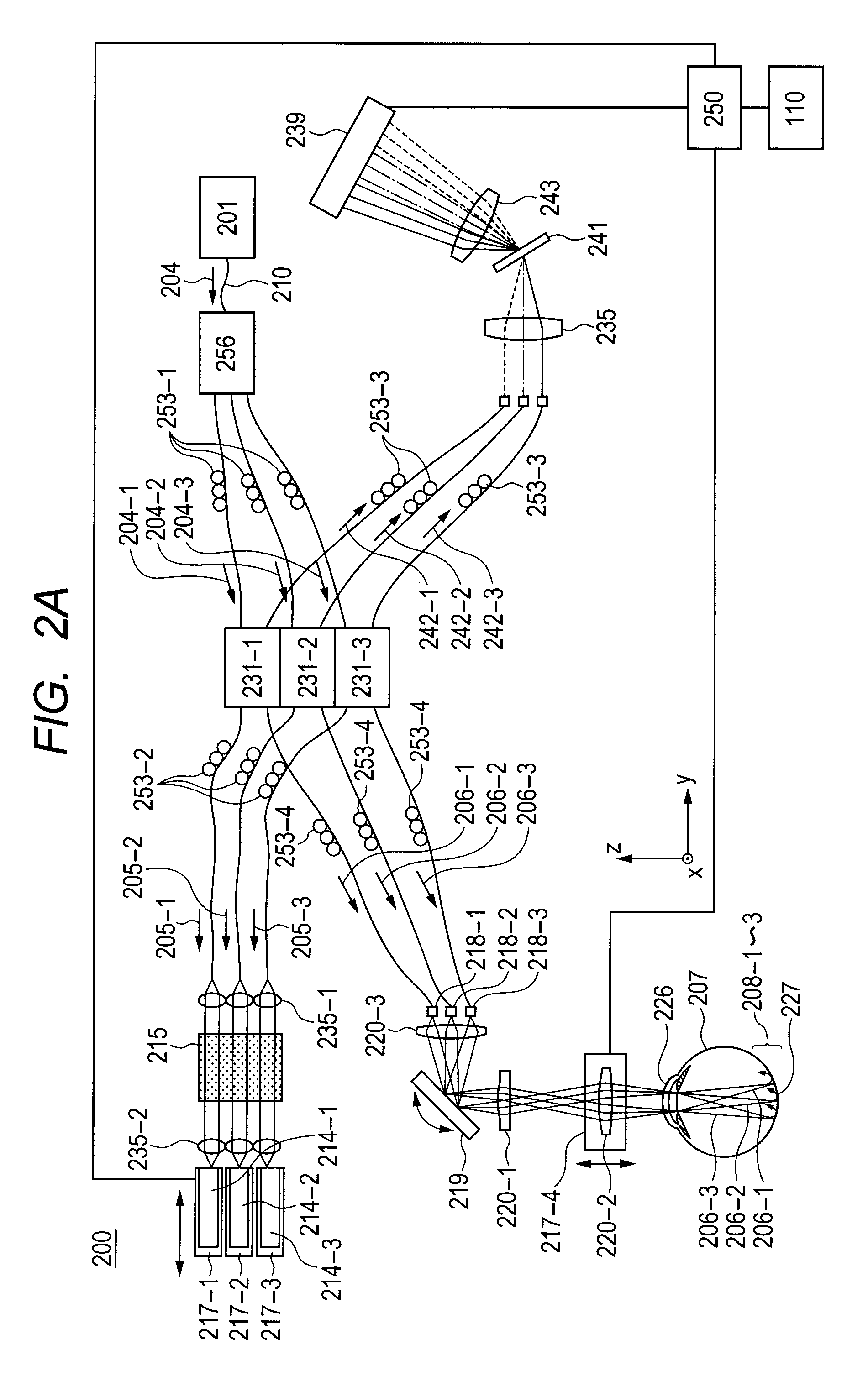
[0035]FIG. 1 is a diagram illustrating a configuration of an image processing system 100 including an image processing apparatus 110 according to this embodiment. As illustrated in FIG. 1, the image processing system 100 has a configuration in which the image processing apparatus 110 is connected to a tomographic image photographing apparatus ...
second embodiment
[0073]In the first embodiment described above, the parameter of the shape model is determined from an arbitrary set of the tomographic images (one set is the three tomographic images in a second embodiment of the present invention) when the shape model is determined. Then, as for other tomographic image sets, alignment in the depth direction is performed according to a difference between the determined shape model and the retina layer position of each tomographic image. In this embodiment, description is given of a case where the shape model parameter and a parallel movement amount parameter in each tomographic image set are determined so as to correct the volume image deformation by using all sets of the tomographic images (N sets in this embodiment). In this embodiment, the case where the shape model is the second order curved surface is described. Then, as a method of determining the parameter, description is given of a method in which the shape model parameter and the parallel m...
third embodiment
[0082]In the first and second embodiments described above, the entire retina layer is detected, and the shape model is estimated by using an arbitrary coordinate point or the detected entire coordinate point data. In a third embodiment of the present invention, there is described a case where a coordinate point to be used for estimating the shape model is selected, and the shape of the object to be inspected is restored by using the selected coordinate point. Hereinafter, with reference to FIG. 8, a process procedure of the detection unit 131 in this embodiment is described.
[0083](Step S801)
[0084]In Step S801, image conversion of a tomographic image is performed. In this embodiment, a median filter and a Sobel filter are applied to the tomographic image so as to generate a median image and a Sobel image, respectively. In this embodiment, a pixel value becomes larger as a signal intensity becomes higher, while the pixel value becomes smaller as the signal intensity becomes lower.
[008...
PUM
 Abstract
Description
Claims
Application Information
 - R&D
- Intellectual Property
- Life Sciences
- Materials
- Tech Scout
- Unparalleled Data Quality
- Higher Quality Content
- 60% Fewer Hallucinations
Browse by: Latest US Patents, China's latest patents, Technical Efficacy Thesaurus, Application Domain, Technology Topic, Popular Technical Reports.
© 2025 PatSnap. All rights reserved.Legal|Privacy policy|Modern Slavery Act Transparency Statement|Sitemap|About US| Contact US: help@patsnap.com


