Liquid scintillator for 3D dosimetry for radiotherapy modalities

a scintillator and liquid technology, applied in the direction of instruments, calibration apparatus, x/gamma/cosmic radiation measurement, etc., can solve the problems of limited use of scintillating materials in scanning beam proton therapy, and achieve the effect of quick and accurate comparison

Active Publication Date: 2015-05-12
BOARD OF RGT THE UNIV OF TEXAS SYST
View PDF11 Cites 19 Cited by
  • Summary
  • Abstract
  • Description
  • Claims
  • Application Information

AI Technical Summary

Benefits of technology

[0004]Liquid scintillator detectors (“LSDs”) are provided that produce dose verification to meet quality assurance requirements of a broad range of complex radiotherapy modalities such as intensity-modulated radiotherapy (“IMRT”) for photon radiotherapy and intensity-modulated proton therapy (“IMPT”) for proton therapy. The LSDs can be used to quickly and accurately compare a 3D dose distribution with the planned dose distribution obtained from a treatment planning system. The LSDs can be used on a regular basis to perform the mandatory patient-specific treatment verification in a faster (i.e., only a single irradiation is required) and more thorough (i.e., a complete assessment of the 3D dose distribution is performed) manner than what is currently used as the standard of care. For applications with charged particles such as proton pencil beams, this system and associated methodologies can be used to measure the range, the pencil beam position, and the intensity of the beam. The resulting information can then be used to reconstruct a complete 3D dose distribution.

Problems solved by technology

Use of scintillating materials in scanning beam proton therapy have been limited to two-dimensional (“2D”) scintillation.

Method used


Image

  • Liquid scintillator for 3D dosimetry for radiotherapy modalities
  • Liquid scintillator for 3D dosimetry for radiotherapy modalities
  • Liquid scintillator for 3D dosimetry for radiotherapy modalities

Examples


example 1

Materials and Methods

Detector System

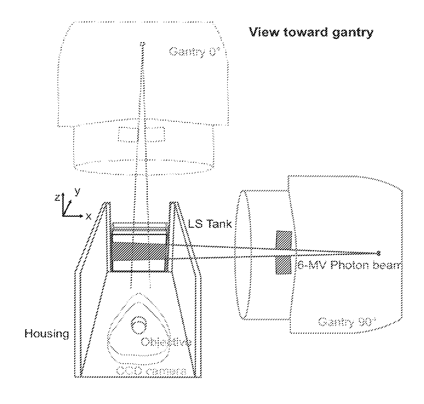
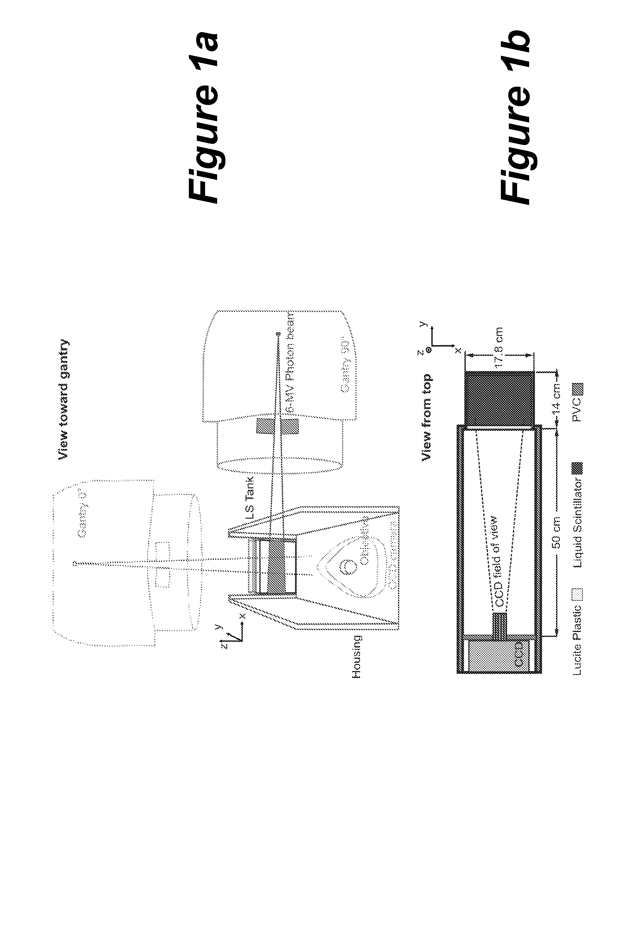
[0046]The detector system consisted of a light shielded, LS-filled acrylic tank (outer dimensions: 17.8×14.0×12.7 cm3, 3 mm wall thickness), a camera objective and a high sensitivity electron-multiplying CCD camera (Luca EM, And or Technology, South Windsor, Conn.) and is shown in FIG. 1. A housing box, made of dark PVC, enclosed all components and insulated the inner compartment from ambient light. A regular 25 mm camera objective (JML Optical Industries, Inc., Rochester, N.Y.) with adjustable focal length and variable aperture (F-number=0.95-22) was mounted onto the camera's front to focus the acquired image to the CCD chip. The chip had a resolution of 658×496 pixels and a color depth of 14 bits, thus providing 16,383 gray scale levels and allowing for a large dynamic range for image processing. The distance between the tip of the camera objective and the center of the tank was 55 cm, which resulted in a pixel size of 0.22 mm or a field of view...

example 2

Materials and Methods

[0080]The detector system was developed in-house and consisted of a rectangular light-tight gray PVC phantom containing an acrylic tank filled with LS and a CCD camera as shown in FIG. 9. The organic LS material used in this study was BC-531 (Saint Gobain Crystals, Newbury, Ohio, USA). The physical characteristics of this material are shown in Table 3.

[0081]

TABLE 3Physical characteristics of the Liquid Scintillator BC-531compared to the BC-400 plastic scintillator, polystyrene and water.BC-531BC-400PolystyreneWaterEmission (% of anthracene)5965N / AN / APeak wavelength (nm)425423N / AN / AElectron density (1023 e / g)2.9303.2723.2383.343Specific gravity (g / cm3)0.8701.0321.0601Composition1:11.981:8.4701:7.7401:11.19[Z:fraction by weight (%)]6:88.026:91.536:92.268:88.81

[0082]The BC-531 LS light yield emission is compared to anthracene, an organic crystal commonly used as the standard for scintillators. Comparison of the LS with water, polystyrene and the most standard plast...


PUM


Abstract

A liquid scintillator detector for three-dimensional dosimetric measurement of a radiation beam is provided wherein a volumetric phantom liquid scintillator is exposed to the radiation beam to produce light that is captured by the cameras that provide a three-dimensional image of the beam.

Description

CROSS-REFERENCE TO RELATED APPLICATIONS[0001]This application is a national phase application under 35 U.S.C. §371 of International Application No. PCT / US2010 / 041216 filed Jul. 7, 2010, which claims priority to U.S. Provisional Patent Application Ser. No. 61 / 223,619 filed Jul. 7, 2009. The entire text of each of the above-referenced disclosures is specifically incorporated herein by reference without disclaimer.STATEMENT REGARDING FEDERALLY SPONSORED RESEARCH OR DEVELOPMENT[0002]This invention was made with government support under CA120198-01 awarded by the National Institute of Health. The government has certain rights in the invention.BACKGROUND OF THE INVENTION[0003]Use of scintillating materials in scanning beam proton therapy have been limited to two-dimensional (“2D”) scintillation. Three dimensional (“3D”) scintillation has been only used in brachytherapy applications using radioactive sources to study the dosimetric properties of different scintillating solutions with the a...

Claims


Application Information

Patent Timeline
Patent Type & Authority Patents(United States)
IPC IPC(8): G12B13/00G01T1/04G01T1/204
CPCG01T1/04G01T1/204
Inventor BEDDAR, A. SAMMOHAN, RADHEGILLIN, MICHAELARCHAMBAULT, LOUISPOENISCH, FALK
Owner BOARD OF RGT THE UNIV OF TEXAS SYST
Why Eureka
Try Eureka