Injector apparatus and method for drug delivery

a technology which is applied in the field of injectors and injectors, can solve the problems of poor patient comfort, limited penetration of eye drops into the external tissue of the eye, and prior methods and apparatus for treating eye diseases can be less than ideal, and achieve the effect of high resistance to flow

Active Publication Date: 2015-05-19
FORSIGHT VISION5 INC
View PDF531 Cites 80 Cited by
  • Summary
  • Abstract
  • Description
  • Claims
  • Application Information

AI Technical Summary

Benefits of technology

[0009]Embodiments of the present invention provide improved methods and apparatus to provide a therapeutic fluid to devices implanted in the body, for example to containers of devices implanted in the eye of a patient. The methods and apparatus may comprise an injector to increase an amount of therapeutic agent injected into the device implanted in the eye, or a structure to receive the therapeutic fluid within the device implanted in the eye, or combinations thereof. The device implanted in the eye may comprise a reservoir chamber coupled to a porous structure so as to release the therapeutic agent for an extended time. In many embodiments, the volume of the reservoir chamber is sized to fit within the eye without substantially affecting vision. The porous structure may have a high resistance to flow, and in many embodiments the therapeutic fluid injected into the device may be exchanged with a fluid of the device implanted in the eye.
[0010]In many embodiments, the container implanted in the eye comprises a fluid having a density different than the fluid therapeutic fluid of the container implanted in the body. The therapeutic fluid may comprise a formulation of a therapeutic agent having a density greater than a fluid of the device implanted in the eye, such that the therapeutic formulation injected into the implanted chamber may separate at least partially. In many embodiments, the at least partial separation of the therapeutic fluid from the fluid of the implanted device can be used to improve an efficiency of exchange of the therapeutic fluid with the fluid of the chamber, so as to increase the amount of therapeutic fluid in the chamber. While the methods and apparatus as described herein can be used with many devices to increase the amount of therapeutic fluid in the implanted device, the increased the efficiency can be especially beneficial with implanted devices having a reservoir chamber comprising a substantially constant volume. Also, with implants located at least partially in the vitreous humor of the eye, the size of the reservoir chamber can somewhat limited to provide a clear optical path for vision, and the embodiments described herein can be used to increase the amount of fluid placed in the chamber so as to increase the therapeutic benefit of the implanted device and provide sustained release for an extended time.
[0011]In many embodiments, one or more of the therapeutic device or the injector can be configured to increase the amount of therapeutic fluid placed in the device based on the at least partial separation. The injector may comprise a first channel sized to extend to a first opening at a first location of the implanted device reservoir chamber so as to pass the therapeutic fluid into the chamber, and a second channel can be sized to extend to a second opening at a second location of the implanted device chamber so receive the fluid of the implanted device, such that the efficiency of the exchange can be increased based on the at least partial separation and the separation of the first location and the second location. The first channel may comprise a first lumen of at least one needle, and the second channel can be sized and shaped in many ways and may comprise a second lumen of the at least one needle. The second opening may comprise a vent to receive fluid from the chamber of the therapeutic device and inhibit excessive pressurization of the reservoir chamber so as to maintain substantially the integrity and function of the therapeutic device implanted in the eye.

Problems solved by technology

The prior methods and apparatus for treating diseases of the eye can be less than ideal in at least some instances.
For example, eye drops may have limited penetration of the external tissue of the eye, such that at least some therapeutic agents may not be delivered effectively with eye drops in at least some instances, for example high molecular weight therapeutic agents.
Further, drops administered to the eye may not remain in the tear of the eye as long as would be ideal and can be washed away, for example when the patient blinks so as to provide less than ideal therapeutic benefit in at least some instance.
However, in at least some instances, the therapeutic agent of the implantable device can be depleted, and the device may be removed or additional therapeutic agent placed in the device.
Prior methods and apparatus to place a therapeutic fluid in a device implanted in the eye can provide less than ideal results in at least some instances.
For example, the amount of therapeutic agent placed in the device may be less than ideal in at least some instances.
Further at least some of the prior methods to place of a therapeutic fluid in a device implanted in an eye may take longer than would be ideal.
In at least some instances, the fluid placed initial in the device may be forced out of the therapeutic device, such that the amount of therapeutic agent placed in the treatment device can be less than ideal for sustained release of the therapeutic agent.
In at least some instances the injected fluid may comprise amounts of therapeutic agent that may be not be suitable for direct contact with tissue, such that leakage, or potential leakage, may limit available treatment options.

Method used


Image

  • Injector apparatus and method for drug delivery
  • Injector apparatus and method for drug delivery
  • Injector apparatus and method for drug delivery

Examples


experiment 1

Refill Efficiency Studies with Fluids Having Different Densities

[0506]Trehalose buffer was prepared containing 10 wt % trehalose (Fisher), 0.01 wt %% polysorbate 20 (Fisher) and 10 mM histidine HCl (Spectrum). The pH was adjusted to 7.6 using sodium hydroxide. Fluorescein sodium (AngioFluor) was added to a final concentration of 2.5 wt %. Phosphate buffered saline (hereinafter “PBS”, Sigma) was prepared in HPLC grade water and an aliquot of this had fluorescein added to reach a final concentration of 2.5 wt %. Density measurements were made at 23° C. gravimetrically using a 10 mL Class A volumetric flask and an analytical balance measuring to 0.01 mg.

[0507]This study used devices with 25 uL reservoir volume and titanium porous structures that produce drug release profiles corresponding to a Release Rate Index of 0.02 mm. Devices were initially filled with 25 uL of PBS using a 1 cc tuberculin syringe (BD) and a 33 G needle (TSK). The distal end of the filled devices was inserted into...

experiment 2

Video Imaging and Efficiency Studies

[0513]Video imaging studies with a marker dye were conducted to identify the at least partial separation as described herein.

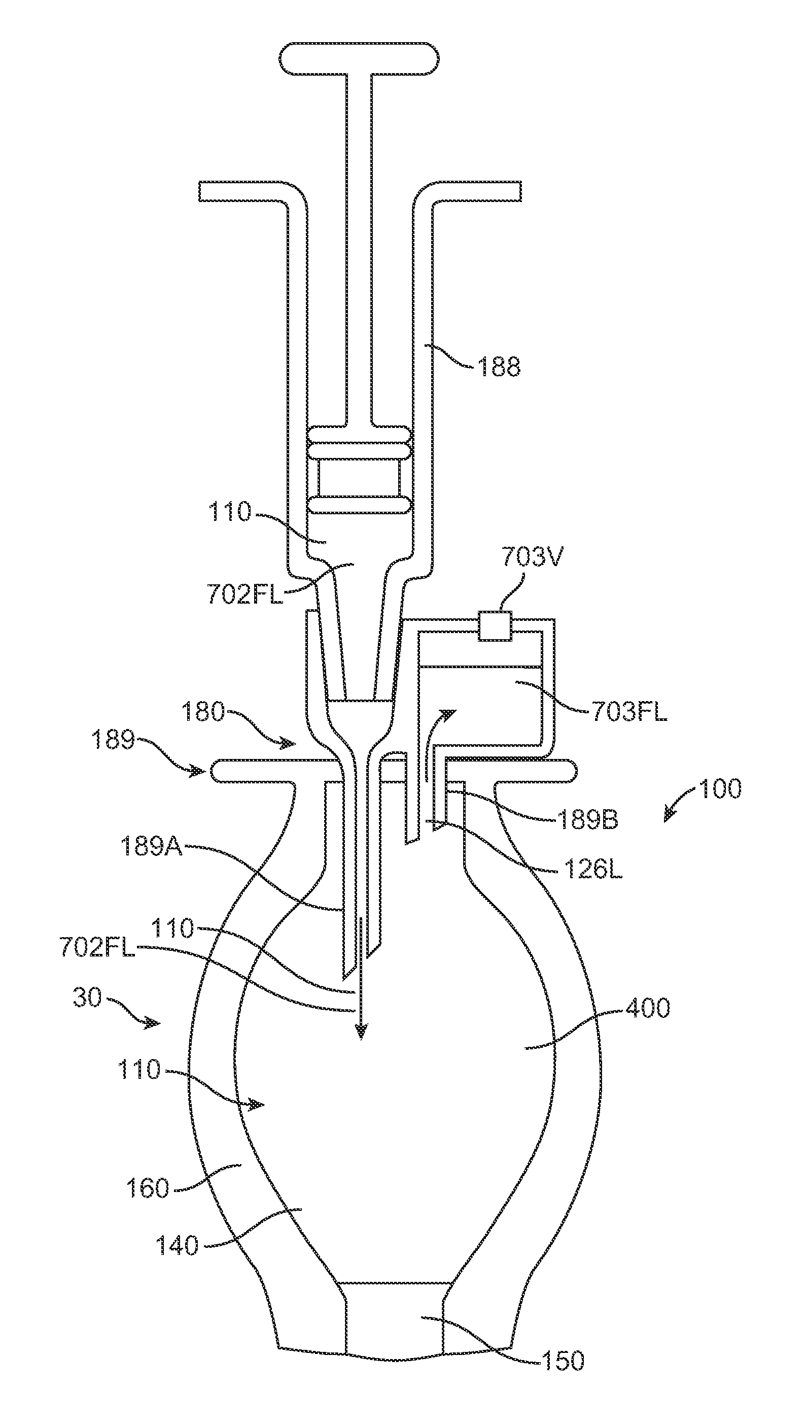
[0514]The exchange needle comprised a coaxial needle system in accordance with the embodiments of FIGS. 7-1 and 7-2, and having an internal needle of 33½ gauge and an outer tube of 0.018″ inner diameter. The length of the inner needle was within a range from about 0.15 to about 0.25″ long. The length of the outer tube used in the study was within a range from about 0.04″ to about 0.09″ long so as to provide a majority of the resistance to flow along the vent fluid path.

[0515]FIGS. 15A-1 to 15A-3 show the therapeutic device in an angle up position (10 degrees up off the horizontal, porous structure above penetrable barrier). The concentric needle and vent of the injector apparatus was constructed in accordance with the apparatus shown in FIGS. 7-1 and 7-2 as described herein. The injector apparatus injected denser liquid thro...

experiment 4

Refill Efficiency and Density

Experiments 4-1 to 4-3

[0523]Additional studies were conducted to determine refill efficiency with the porous structure above or below the injection port. The substantially rigid implantable devices comprised a reservoir volume of 25 uL and were filled initially with PBS having a density of approximately 1.00, as described in Experiment 1. These devices were injected with 45 uL of fluid to determine the efficiency of the injection based on the amount of injected liquid in the reservoir chamber implantable device upon completion of the injection. As used in these studies, device up refers to the porous structure located above the penetrable barrier of the injection port. Experiments 4-1 to 4-2 used a single approximately 33 Gauge needle extending into the device and Experiment 4-3 used an exchange apparatus comprising a needle and a vent placed within the chamber of the device as shown in FIGS. 7-1 and 7-2. The injected solution was at least about 3% dense...


PUM


Abstract

Methods and apparatus provide a therapeutic fluid to devices implanted in the body, for example to containers of devices implanted in the eye of a patient. The methods and apparatus may comprise an injector to increase an amount of therapeutic agent injected into the device implanted in the eye, or a structure to receive the therapeutic fluid within the device implanted in the eye, or combinations thereof. The device implanted in the eye may comprise a reservoir chamber having a fluid with a density different than the therapeutic fluid, and the apparatus can be adapted to at least partially separate the implanted device fluid from therapeutic fluid within the reservoir chamber to increase and amount of therapeutic fluid placed in the reservoir chamber.

Description

CROSS-REFERENCES TO RELATED APPLICATIONS[0001]The present PCT patent application claims priority to the following U.S. Patent Applications 61 / 371,154, entitled “INJECTOR APPARATUS AND METHOD FOR DRUG DELIVERY”, filed 5 Aug. 2010; U.S. Patent App. Ser. No. 61 / 499,095, entitled “Injector Apparatus and Method for Drug Delivery”, filed Jun. 20, 2011; U.S. Patent App. Ser. No. 61 / 501,021, entitled, “Injector Apparatus and Method for Drug Delivery”, filed: Jun. 24, 2011; U.S. Patent App. Ser. No. 61 / 504,038, entitled “Injector Apparatus and Method for Drug Delivery”, filed Jul. 1, 2011; 61 / 371,169, entitled IMPLANTABLE THERAPEUTIC DEVICE”, filed on 5 Aug. 2010; U.S. Patent App. Ser. No. 61 / 495,251, entitled “Diagnostic Methods and Apparatus”, filed, Jun. 9, 2011; and U.S. Patent App. Ser. No. 61 / 495,718, entitled “Diagnostic Methods and Apparatus” filed, Jun. 10, 2011; the full disclosures of which are incorporated herein by reference.STATEMENT AS TO RIGHTS TO INVENTIONS MADE UNDER FEDERA...

Claims


Application Information

Patent Timeline
Patent Type & Authority Patents(United States)
IPC IPC(8): A61M5/178A61F9/00A61M5/142A61M5/31A61M39/02
CPCA61F9/0008A61F9/0017A61M5/14276A61M5/178A61M5/31A61M39/0208A61M39/0247A61M2039/027A61M2039/0276A61F9/00A61M5/32A61M5/46
Inventor DE JUAN, JR., EUGENEALSTER, YAIRFARINAS, KATHLEEN COGANMACFARLANE, K. ANGELAREICH, CARY J.CAMPBELL, RANDOLPH E.DOUD, DARRENERICKSON, SIGNEBARRETT, MIKEBATTEN, DAVIDSKIELLER, CHRISTINASTINE, GREG
Owner FORSIGHT VISION5 INC
Why Eureka
Try Eureka