Method for fixing a bearing ring on or in a component

a technology for bearing rings and components, applied in the direction of couplings, mechanical devices, rigid support of bearing units, etc., can solve the problems of low precision, large economic cost of attachment, and requirement of at least three components, and achieve the effect of stable adhesive bonding

Inactive Publication Date: 2015-05-19
AB SKF
View PDF8 Cites 1 Cited by
  • Summary
  • Abstract
  • Description
  • Claims
  • Application Information

AI Technical Summary

Benefits of technology

[0031]The proposed methodology offers the advantage that a stable adhesive bond is producible in a cost-effective way. Different materials with different material characteristics can be bonded with each other in a problem-free way.

Problems solved by technology

Of course the economic costs for the realization of the attachment also play a large role.
Furthermore, it is disadvantageous with the attachment using an adapter sleeve that at least three components are required for the attachment.
These must have a relatively high precision, which causes corresponding costs.
In addition to the manufacturing expenses and costs, multiple components also mean an accumulation of manufacturing tolerances.
Depending on the situation of the actual dimensions, these can add up unfavorably.
A further problem in the mounting of an adapter sleeve is that the cross-section of the sleeve, for strength reasons, must be chosen to be so large that, with the exception of incorporated adapter sleeves (special sleeves), the respective next larger bearing number must be chosen, in order not to weaken the bearing ring too much on the other side.
This fact restricts the flexibility of construction.
Especially with performance increases (e.g. with higher rotational speeds) of machines, which require a higher running accuracy, this means that the application can no longer be constructed as compactly.
A specific problem with the use of adapter sleeves is that the desired location of the bearing during mounting over the insertion can only be defined with difficulty.
With the use of screw connectors and eccentric rings, the problem is that, due to this attachment possibility, a tilting of the bearing ring towards a shaft-shaped component can occur.
This leads to a reduced running smoothness and / or running accuracy.
Furthermore there is the problem that the type of fastening may not be sufficient relative to the load to completely prevent micro-movements.
Frictional corrosion with corresponding consequential damage is often observed in the fitted joints of such bearings.
If the attachment is, however, too highly strained, the attachment means (especially the set screw) can be damaged.
With regard to the strength of the attachment of the bearing ring to the component, it is a negative that the transmission of axial forces can be significantly limited.
Especially with the use of set screws, a deformation of the bearing ring also occurs as a result of a too-strong tightening of the screws, which leads to an unfavorable running performance and to strains.
An increased clearance brings with it however in turn the disadvantages of an unfavorable support ratio in the bearing.
Depending on the type of bearing (e.g. especially with deep-groove ball bearings), the extent of the clearance reduction is difficult to control.
This can lead to the bearing being strained radially.
The following is additionally disadvantageous: The set screw achieves its strength through the digging-in into the material of the component (shaft), i.e. through an interference fit.
Since this leads to a bulge on the shaft, the dismounting of the bearing is made more difficult.
A specific problem of the eccentric ring is that a fixed connection can only be achieved through twisting two rings relative to each other.
This means, however, that a breathing of the fitting joint can occur when the rotational direction of the bearing rapidly changes and can thereby loosen the bond.
This method has the disadvantage that the introduction of an adhesive in assembly lines is difficult to design and / or the process reliability—especially with regard to the amount of adhesive to be supplied and with respect to the cleanliness of the joining partner—depends on the conditions during the mounting and / or on each assembly worker.
Furthermore with the previously known solution, there is the disadvantage that, during manual introduction of the adhesive, surrounding components, such as for example seals, can be wetted with adhesive.
The function of such a component can hereby be disadvantageously influenced.
Although a stable adhesive connection can already be produced therewith, which represents an easily handleable technology, due to the separate part a relatively large gap must be provided here between the shaft and the bearing ring, which restricts the adhesive load bearing capacity at least in this region.

Method used


Image

  • Method for fixing a bearing ring on or in a component
  • Method for fixing a bearing ring on or in a component
  • Method for fixing a bearing ring on or in a component

Examples


Embodiment Construction

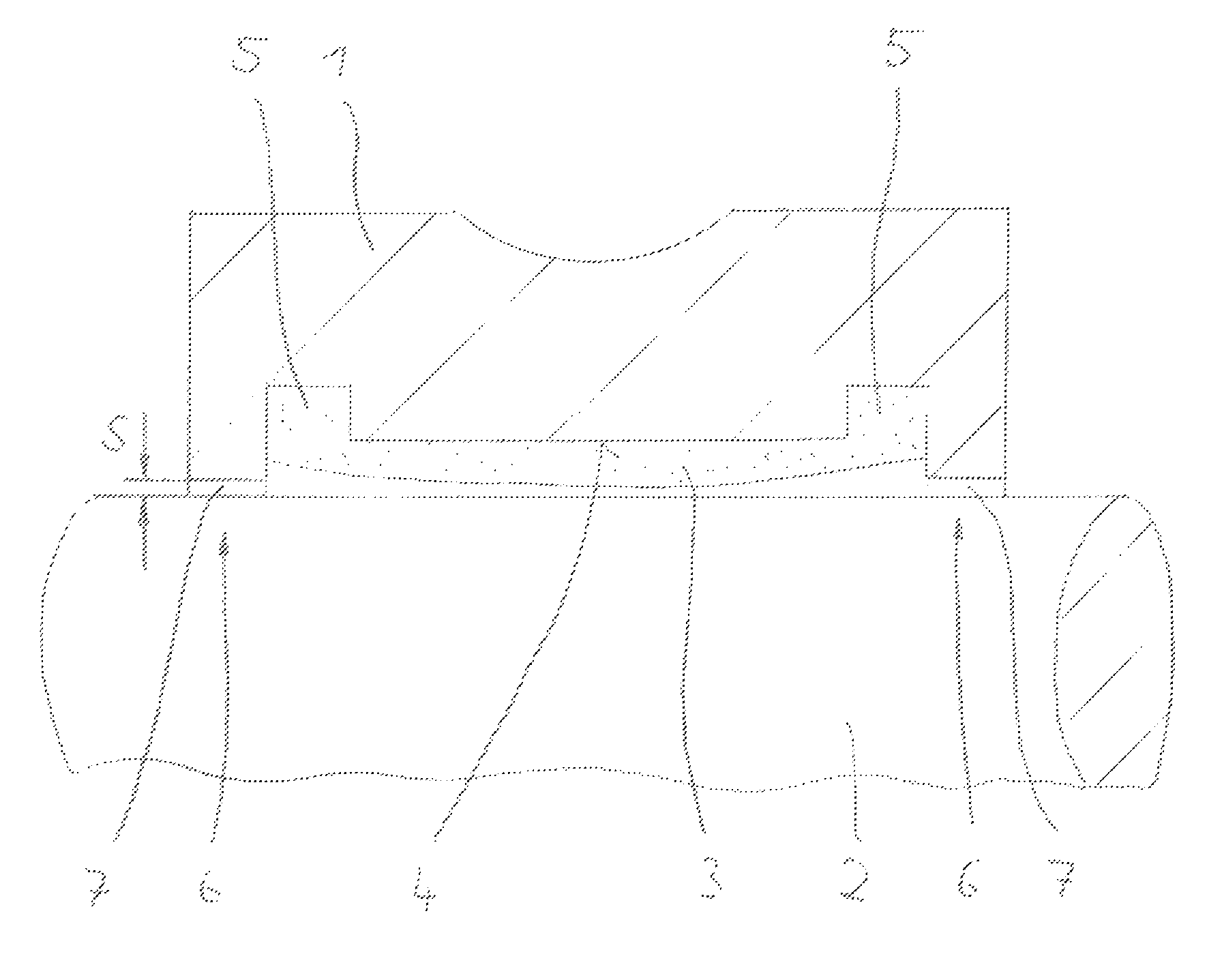
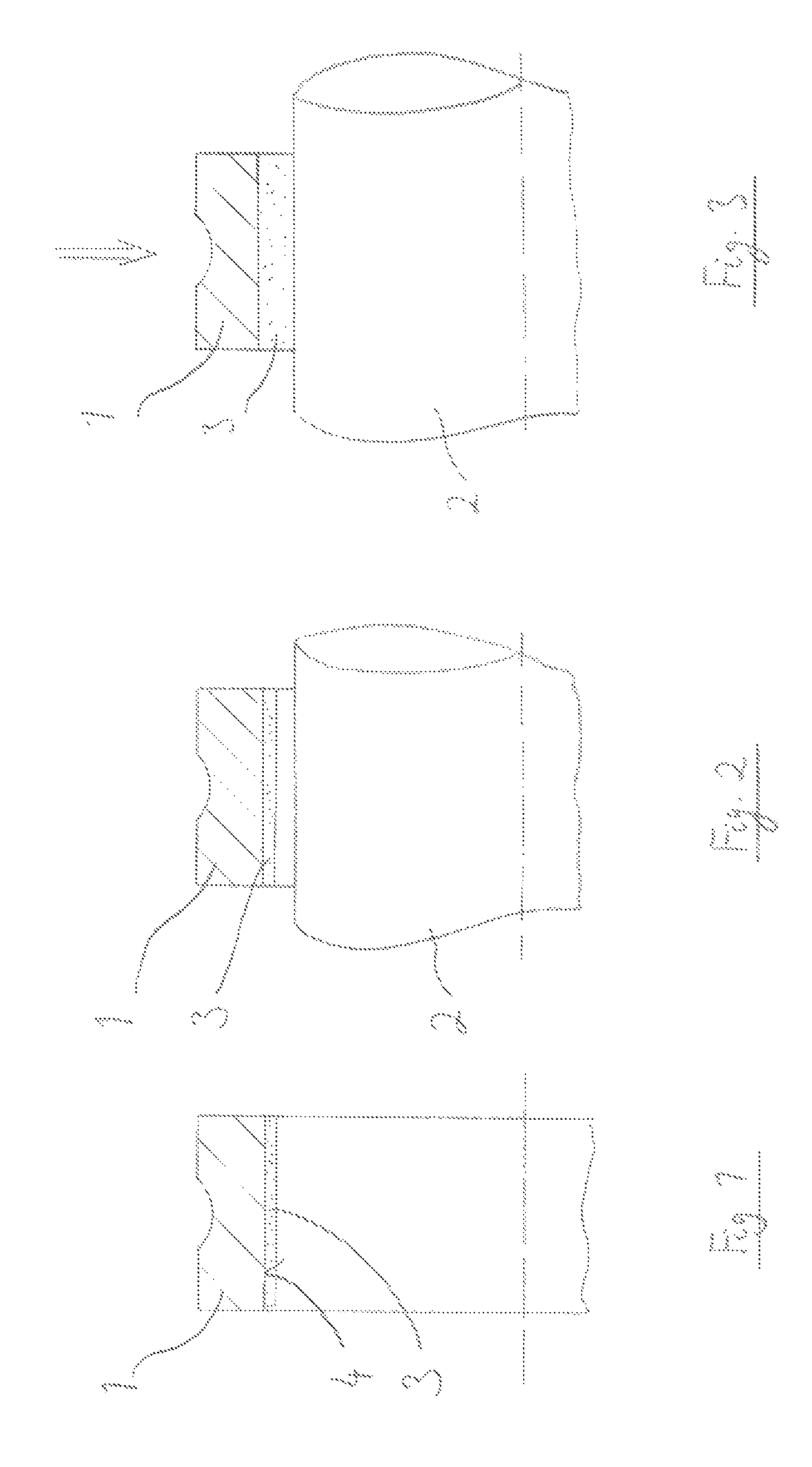
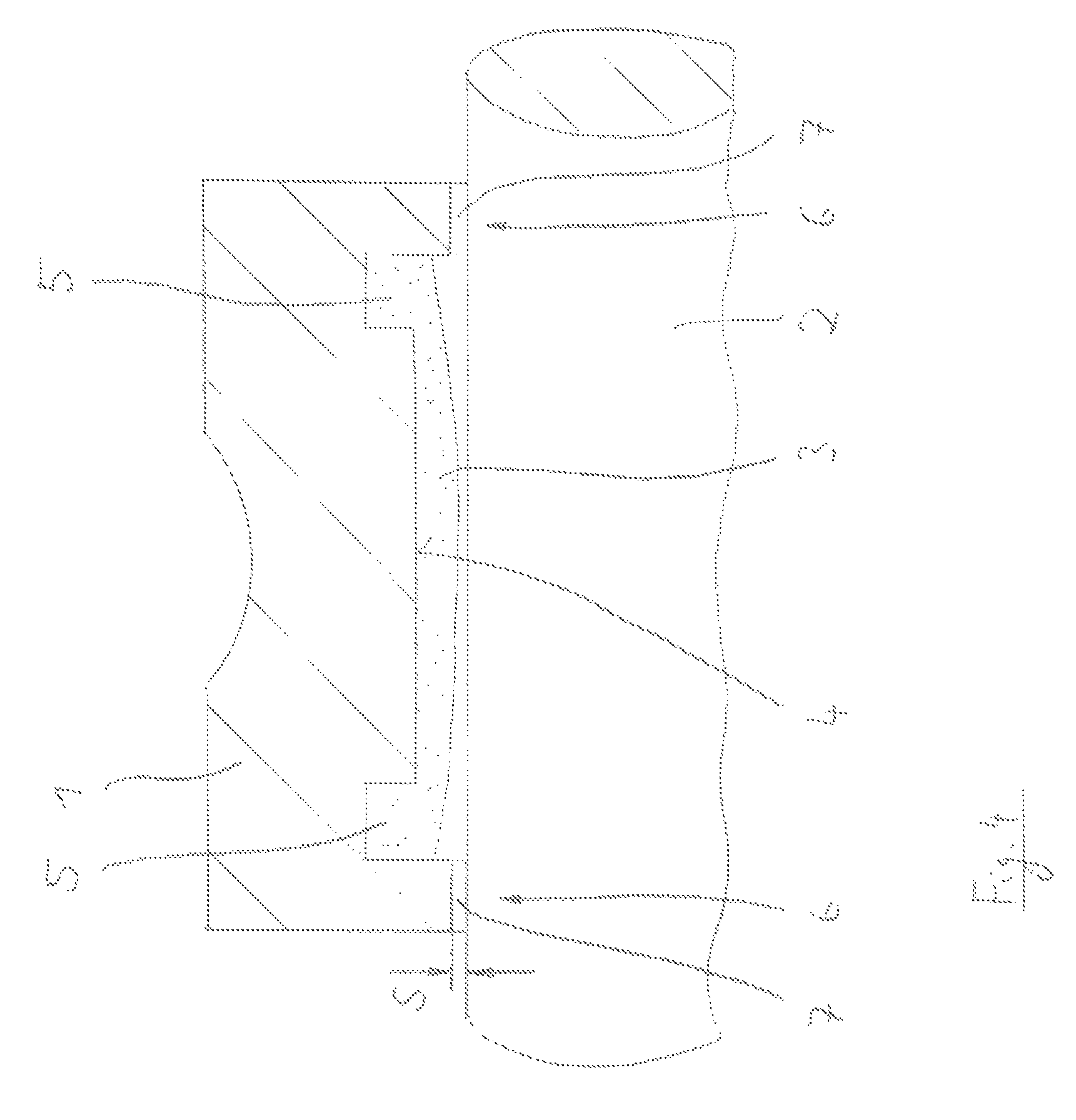
[0037]In FIG. 1 an inner ring 1 of a ball bearing is drawn, which ball bearing is to be connected with a shaft that is not depicted in FIG. 1, and namely through an adhesive process. For this purpose an adhesive 3 is applied to the inner cylindrical surface 4 of the inner ring 1. This adhesive 3 has, when applied to the inner ring 1, a pasty consistency. When it is applied, a pre-curing of the adhesive 3 occurs. This can occur in the air through a sufficiently long holding of the inner ring 1 together with adhesive 3. The adhesive 3“dries” in this way, so that the adhesive layer not only obtains a certain mechanical stability, but also no longer significantly adheres when the adhesive 3 is touched. Accordingly, the further handling of inner ring 1 provided with adhesive 3 is simple, as no special precautions must be taken during the handling and / or during the transport.

[0038]The thus-prepared inner ring 1 (which of course may already be connected with the not-depicted bearing outer ...


PUM

PropertyMeasurementUnit
temperaturesaaaaaaaaaa
glass transition temperatureaaaaaaaaaa

Abstract

A method for fixing a bearing ring on or in a component includes applying an adhesive to a surface of the bearing ring having a least one annular groove-shaped receiving space defined therein such that the adhesive at least partially fills the at least one annular groove-shaped receiving space. The adhesive is allowed to pre-cure on the surface until the adhesive is no longer sticky and then the bearing ring and the component are joined in a desired relative position, such a radial distance between a base of the at least one annular groove-shaped receiving space and the component is larger than a radial distance between the surface and the component. The adhesive is then activated so that the adhesive increases in volume and produces an adhesive bond between the bearing ring and the component.

Description

CROSS-REFERENCE[0001]This application is the U.S. national stage of International Application No. PCT / EP2011 / 050089 filed on Jan. 5, 2011, which claims priority to German patent application no. 10 2010 004 792.9 filed on Jan. 16, 2010.TECHNICAL FIELD[0002]The invention relates to a method for fixing a bearing ring on or in a component using an adhesive connection.RELATED ART[0003]In various cases, e.g. with the use of long, rotatably-supported shafts, the free positionability and a fixed seat of the bearing on the component to be rotatably-supported are very important when assembling rolling-element bearings. Of course the economic costs for the realization of the attachment also play a large role.[0004]First, mechanical solutions are known and common for the fixing. Here adapter sleeves are used, which produce a friction-fit connection over a tapered seat. Further, eccentric rings are known, with which a fixed bond can be produced between the bearing and the component to be rotatab...

Claims


Application Information

Patent Timeline
Patent Type & Authority Patents(United States)
IPC IPC(8): B29C65/02C09J5/00F16B11/00F16C19/06F16C35/063F16D1/068
CPCB29C65/02F16C35/063C09J5/00F16D1/068F16C19/06F16B11/008F16C2300/02F16C2226/40F16D2250/0069
Inventor WOHLFEIL, FLORIANMEYER, WILHELM
Owner AB SKF
Why Eureka
Try Eureka