
Transmission type X-ray tube and reflection type X-ray tube

a technology of x-ray tubes and reflections, applied in the direction of x-ray tube targets, x-ray tube targets, convertors, etc., can solve the problems of reducing image contrast, reducing image contrast, and a large portion of useful x-rays, so as to reduce x-radiation

Active Publication Date: 2015-05-19
NANORAY BIOTECH CO LTD
View PDF21 Cites 3 Cited by
  • Summary
  • Abstract
  • Description
  • Claims
  • Application Information

AI Technical Summary

Benefits of technology

[0026]When an x-ray photon beam contains photons whose energies are just above the k-edge of a filtering material, that material strongly absorbs the given photon beam as is well known by those skilled in the art. If a filter substance can be found that has an absorption edge between the Kα and Kβ lines of the incident x-ray photon beam, this substance can be used to significantly reduce the intensity of the Kβ lines relative to the Kα lines and is defined as a Kβ filter.
[0027]The current invention discloses a transmission type x-ray tube designed with a target thickness of between 5 and 500 microns, which can be combined with Kβ filters chosen to provide filtering of both unwanted high energy to improve image quality and unwanted low energy x-rays to reduce patient dose in medical applications.
[0028]The current invention also discloses a reflection type x-ray tube used in medical imaging and in non-destructive test imaging and a filter designed to reduce the dose to considerably lower levels than is possible with low Z material filters such as aluminum or copper without decreasing significantly x-rays useful for imaging while at the same time decreasing high energy photons above the k-lines of the target material of the reflection type x-ray tube.

Problems solved by technology

Unfortunately such filters also filter out a large portion of the useful x-rays.
However, in order to produce such a high flux optimum energy, inevitably higher energy photons above the optimum energy are produced at the same time.
Such high energy photons are unwanted as they decrease image contrast.
Sensor overload is a problem when too many x-rays not essential to making the image impinge on the sensor.
Reflection tubes do not allow for optimization of flux using target thickness and hence are limited to adjusting the thickness and composition of the filter material to provide the same desired results.

Method used


Image

  • Transmission type X-ray tube and reflection type X-ray tube
  • Transmission type X-ray tube and reflection type X-ray tube
  • Transmission type X-ray tube and reflection type X-ray tube

Examples


Embodiment Construction

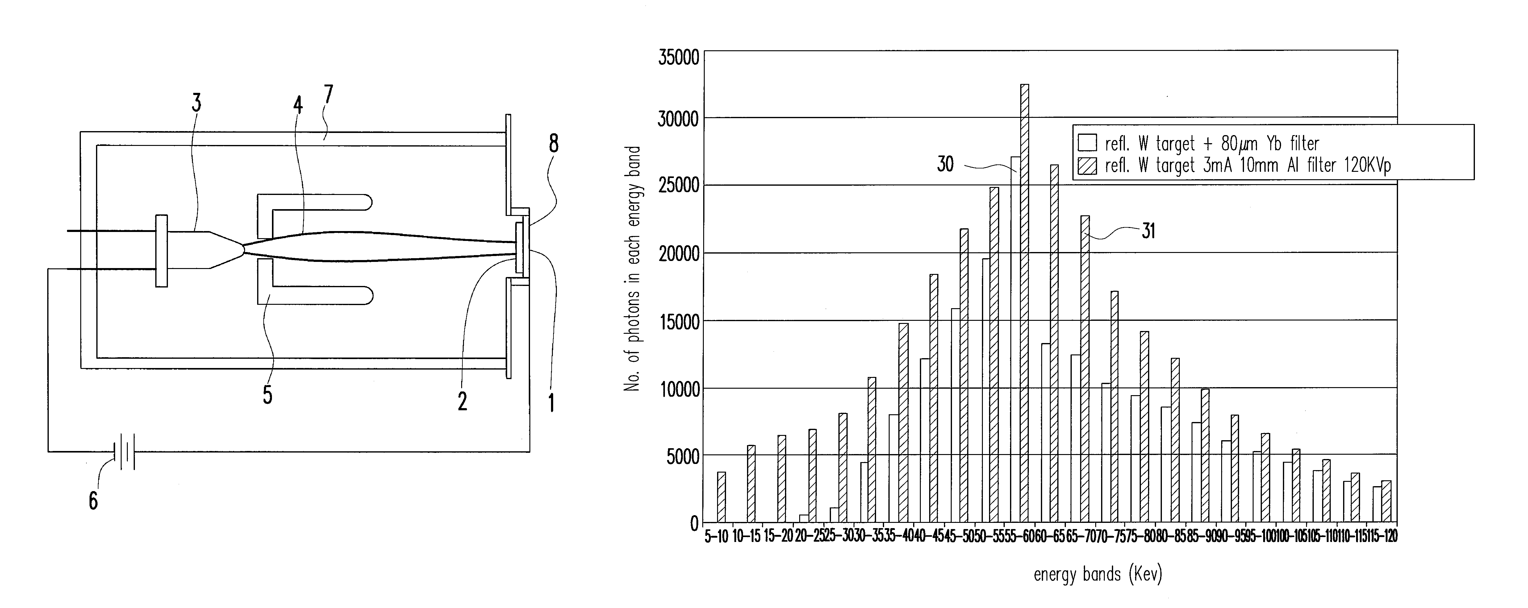
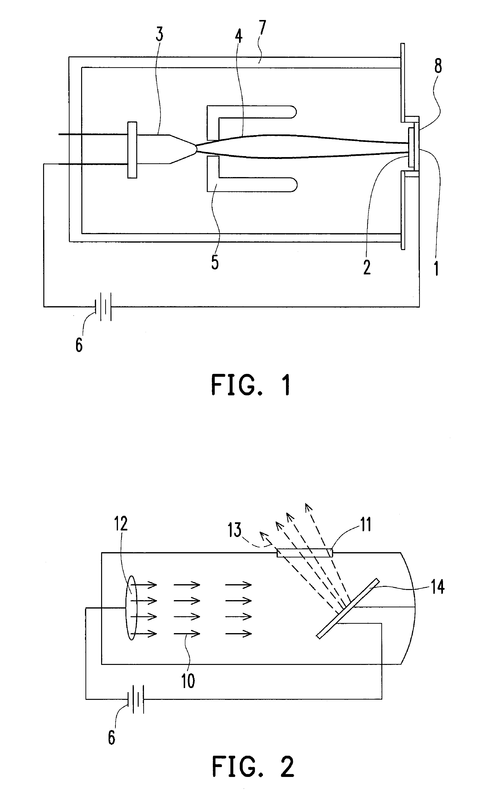
[0044]The transmission x-ray tube of FIG. 1 is comprised of an evacuated housing Item 7, and end-window anode 1 disposed at the end of the housing exposed to atmosphere. An x-ray target foil Item 2 is deposited onto the end-window anode Item 1. In some end-window x-ray tubes the x-ray target and the end-window are made of the same material, eliminating the need for a separate end-window material through which x-rays pass. When a thick target material is sufficiently strong to withhold the x-ray tube vacuum a separate end window material is not needed. An electrically or photon stimulated cathode Item 3 emits electrons, which are accelerated along the electron beam path Item 4 and strike the anode target producing x-rays Item 8. A power supply Item 6 is connected between the cathode and anode to provide the accelerating force for the electron beam. X-rays Item 8 produced exit the x-ray tube through the end-window. An optional focusing mechanism Item 5 typically electrically biased, f...


PUM


Abstract

The present invention provides a transmission type X-ray tube and a reflection type X-ray tube. The transmission type X-ray tube comprises a target and a filter material. The target has at least one element which produces X-rays as being excited. The X-rays comprise characteristic Kα and Kβ emission energies of the element for producing images of an object impinged by the X-rays. The filter material through which the X-rays pass has a k-edge absorption energy that is higher than the Kα emission energies and is lower than the Kβ emission energies. The thickness of the filter material is at least 10 microns and less than 3 millimeters.

Description

CROSS-REFERENCE TO RELATED APPLICATION[0001]This application claims the priority benefit of Taiwan application serial no. 100139390, filed on Oct. 28, 2011. The entirety of the above-mentioned patent application is hereby incorporated by reference herein and made a part of this specification.BACKGROUND OF THE INVENTION[0002]1. Field of the Invention[0003]The present invention generally relates to a transmission type X-ray tube and a reflection type X-ray tube. More particularly, the present invention relates to a transmission type X-ray tube and a reflection type X-ray tube using filter materials to filter out unwanted radiation.[0004]2. Description of Related Art[0005]It is well know in the art of medical imaging that by using low Z filters such as aluminum, molybdenum, yttrium and copper the amount of low energy radiation can be reduced by what is referred to an aluminum equivalent filter thickness. Typically such thickness would range from 0.5 to 12 millimeters of equivalent alum...

Claims


Application Information

Patent Timeline
Patent Type & Authority Patents(United States)
IPC IPC(8): H01J35/00G21K3/00H01J35/02H01J35/08A61B6/00H01J35/18
CPCH01J35/08H01J35/18H01J2235/081H01J2235/087H01J2235/186A61B6/508H01J35/116H01J35/186
Inventor PARSONS, BRUCE BRIANTCHENG, CHI-CHIEH
Owner NANORAY BIOTECH CO LTD
Learn More