Wastewater effluent to geothermal heating

a technology of wastewater effluent and geothermal heating, which is applied in the direction of biological water/sewage treatment, domestic cooling apparatus, lighting and heating apparatus, etc., to achieve the effect of increasing the efficiency of heat pump, increasing the temperature of soil, and increasing the efficiency of heat transfer

Active Publication Date: 2015-05-26
A K INDS
View PDF5 Cites 11 Cited by
  • Summary
  • Abstract
  • Description
  • Claims
  • Application Information

AI Technical Summary

Benefits of technology

[0004]This invention relates to a geothermal heat pump which exchanges heat with wastewater discharged from a home wastewater treatment system. The geothermal heat pump is interconnected with a series of tubes which serve to exchange heat with an attached building. Here, the heat pump's thermal transfer array is buried in close proximity to an array of perforated tubes, or drip field, which discharges wastewater from a wastewater treatment system. The discharged wastewater moistens the soil surrounding the heat pump array thereby increasing the efficiency of heat transfer from the array since heat transfer is generally more efficient from a liquid than a solid. The discharged wastewater also increases the temperature of the soil surrounding the heat transfer array, which further increases the efficiency of the heat pump.
[0005]Increasing the efficiency of a heat pump has many advantages. First, a heat transfer array in contact with moist earth more readily exchanges heat, and so can be sized smaller than an array in contact with dry earth. Second, a smaller heat transfer array requires fewer materials to build, thereby reducing the cost of the system. Third, a smaller heat transfer array requires less excavation during the installation process, both saving money and requiring less disturbance of the surrounding landscaping. Fourth, buildings built on a small parcel of land can benefit from geothermal heating using a small heat transfer array where a traditional heat transfer array may not fit on the property. Additionally, most of the excavation necessary to install heat transfer array is accomplished when a drip field is installed.
[0006]Accordingly, it is an object of the present invention to improve the efficiency of a geothermal heat transfer array through the use of discharge wastewater from a wastewater treatment system to the geothermal heat transfer array.

Problems solved by technology

Third, a smaller heat transfer array requires less excavation during the installation process, both saving money and requiring less disturbance of the surrounding landscaping.
Fourth, buildings built on a small parcel of land can benefit from geothermal heating using a small heat transfer array where a traditional heat transfer array may not fit on the property.

Method used


Image

  • Wastewater effluent to geothermal heating
  • Wastewater effluent to geothermal heating
  • Wastewater effluent to geothermal heating

Examples


Embodiment Construction

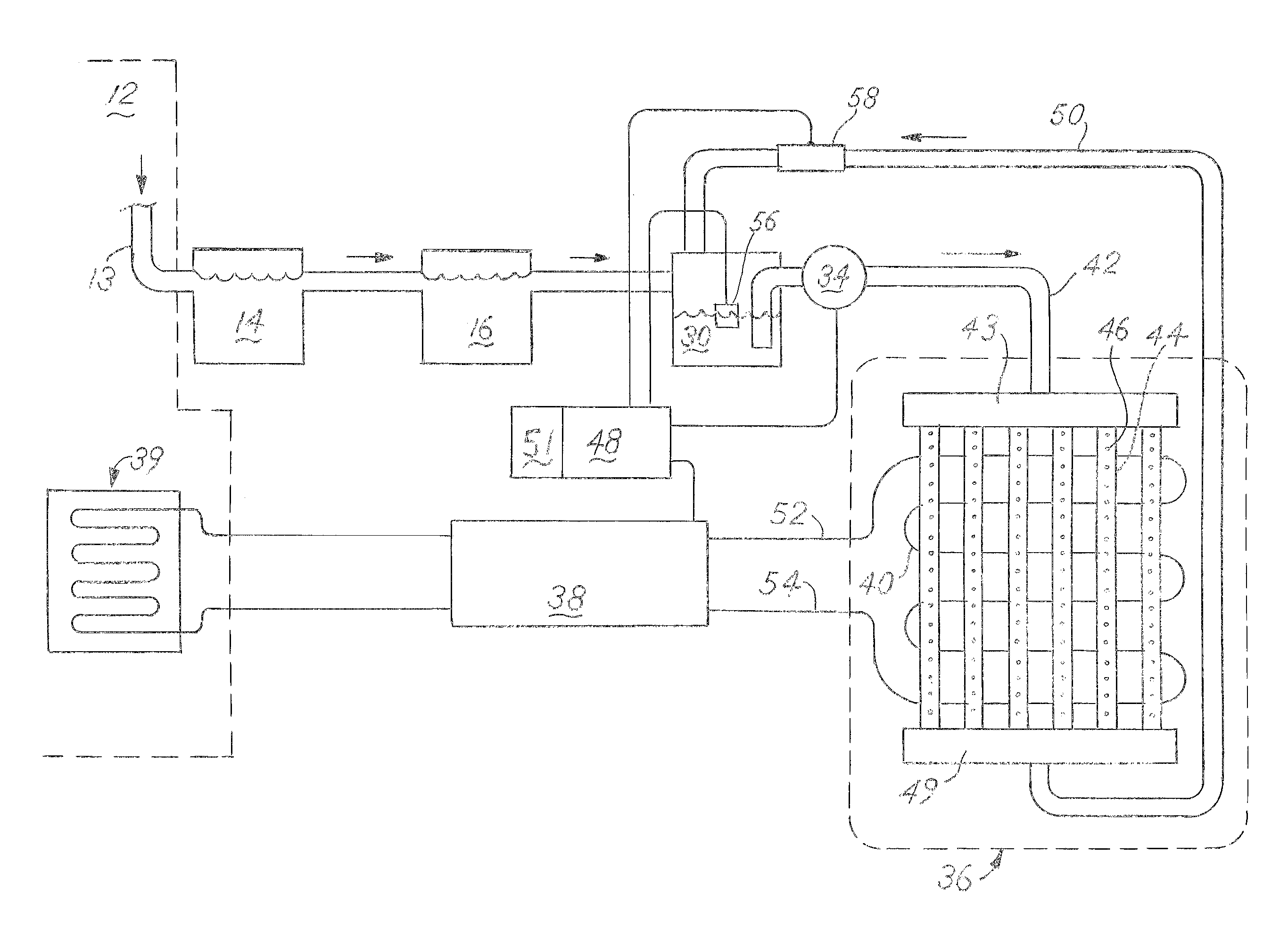
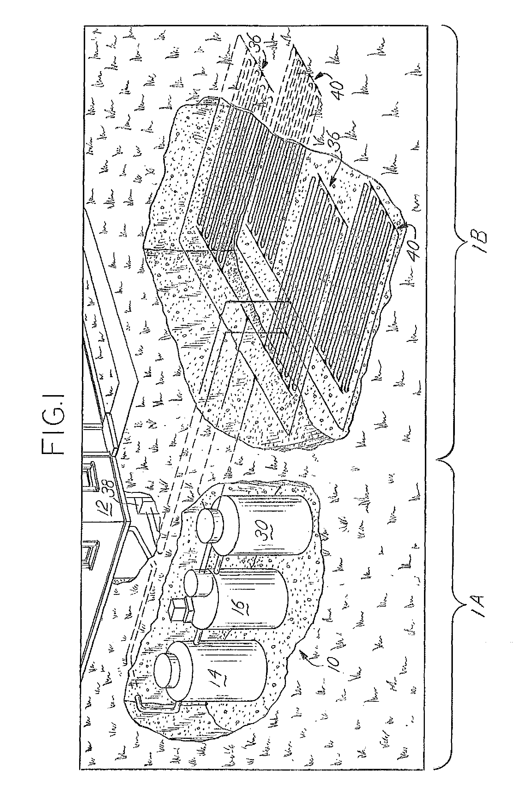
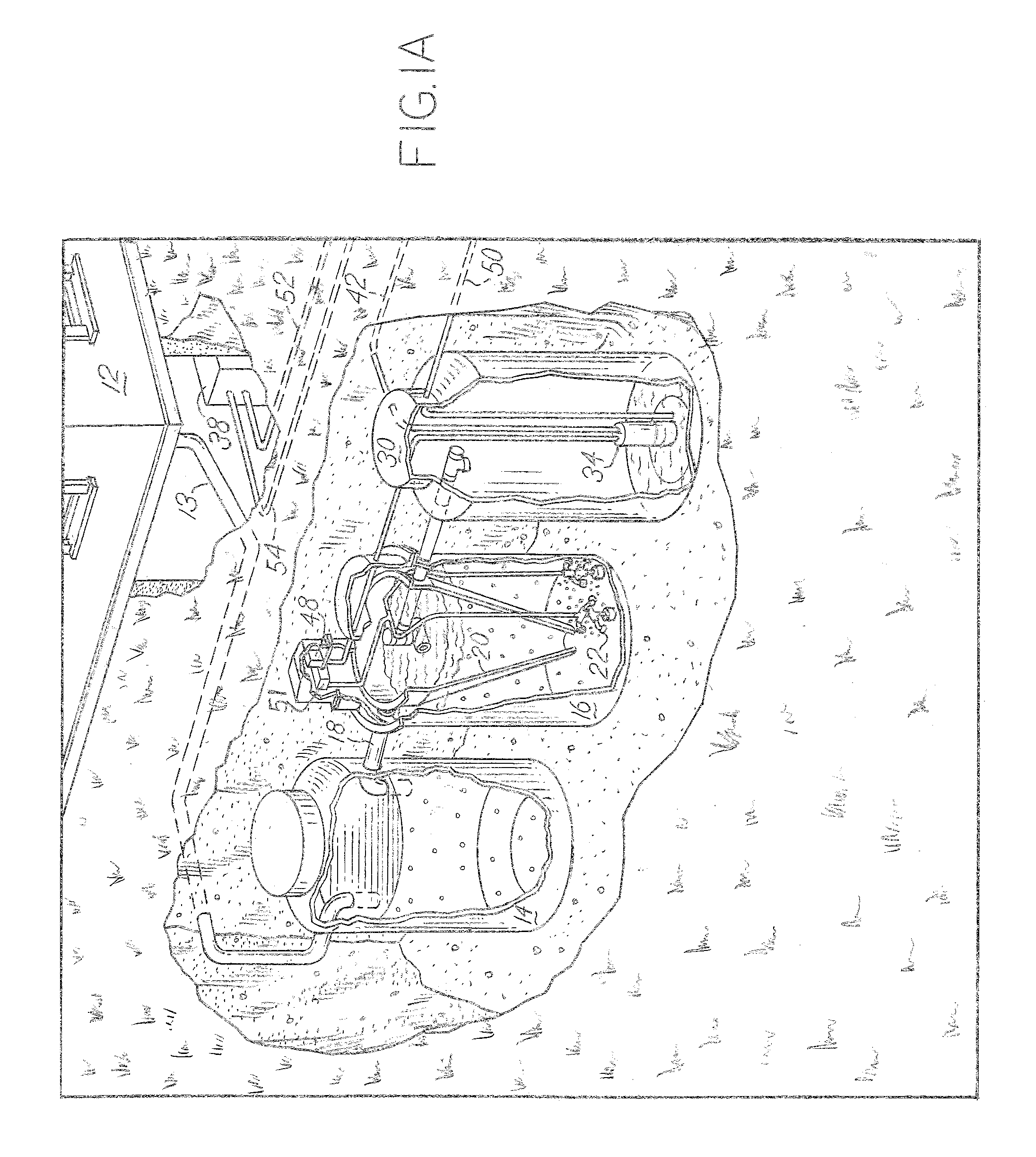
[0015]FIG. 1 shows an overview of the geothermal heating system of the present invention. Wastewater leaves a home 12 through a pipe 13 and enters a wastewater treatment system 10, shown as buried underground. The home 12 could also be a commercial building or other type of temperature-regulated structure. The wastewater treatment system is preferably a series of treatment tanks, as shown in FIGS. 1 and 1A or another similar system which utilizes the aerobic treatment of wastewater. A liquid pump 34 discharges treated wastewater from wastewater treatment system 10 to a drip field 36. Drip field 36 discharges the treated wastewater to the surrounding soil. A heat transfer array 40 is positioned near drip field 36 such that array 40 is in thermal contact with the wastewater discharged from drip field 36. Heat transfer array 40 is integrated with a heat pump 38 which is integrated with a heating or cooling system 39 in home 12.

[0016]In the preferred embodiment, the wastewater treatment...


PUM

PropertyMeasurementUnit
energy efficientaaaaaaaaaa
heataaaaaaaaaa
surface areaaaaaaaaaaa

Abstract

A wastewater geothermal heat system is supplied with processed wastewater through a drip field in proximity to a thermal array part of a geothermal heat pump system. The wastewater treatment system portion provides a periodic source of treated wastewater. Several sensors and a control system regulate a pump that discharges wastewater from the treatment system and enters a drip field where it is released into the surrounding soil. The dampened soil provides an efficient vehicle to transfer heat into or out of a thermal array which is positioned adjacent to the drip field such that it is in contact with the soil that is dampened by the discharged wastewater.

Description

CROSS REFERENCE TO RELATED APPLICATIONS[0001]This application is a Continuation-in-Part of U.S. application Ser. No. 13 / 1333,372 filed Dec. 21, 2011, which is a continuation of Ser. No. 13 / 030,306 filed Feb. 18, 2011, the disclosures of which are hereby incorporated by reference.BACKGROUND OF THE INVENTION[0002]Heat pumps are an efficient way to heat or cool a building and can be more energy efficient than traditional heating and cooling systems. In heating mode, the heat pump moves heat from a source of heat outside the building and introduces that heat into the building's heating system. In cooling mode, the heat pump moves heat from inside the building and relocates that heat out of the building. Heat is transferred to and from the building by pumping a compressible fluid through a heat exchanger. The heat exchanger is commonly configured as a series of pipes which have a large surface area for transferring heat. In many areas, above-ground air is an inadequate and unreliable sou...

Claims


Application Information

Patent Timeline
Patent Type & Authority Patents(United States)
IPC IPC(8): F25D23/12C02F3/12C02F3/28F24J3/08
CPCF24J3/085F24J3/081C02F3/1242C02F3/288Y02E10/14C02F2209/005C02F2209/40C02F2209/42Y02B30/52Y02E10/12F24T10/10F24T10/20F24T10/30Y02E10/10Y02W10/10
Inventor SABO, STEPHEN A
Owner A K INDS
Why Eureka
Try Eureka