Liquid containment system for use with load-supporting surfaces

a technology for containing systems and load supports, which is applied in the direction of applications, containers, ways, etc., can solve the problems of requiring significant time and effort, and it is difficult to find suitable, cost-effective ways to dispose of liners

Active Publication Date: 2015-05-26
NEWPARK MATS & INTEGRATED SERVICES
View PDF10 Cites 20 Cited by
  • Summary
  • Abstract
  • Description
  • Claims
  • Application Information

AI Technical Summary

Benefits of technology

[0006]In some embodiments, the present disclosure involves a system for preventing the leakage of liquid from a reusable, load-supporting surface deployed on the ground without the use of any liners beneath the load-supporting surface. The load-supporting surface includes at least two interconnected planar mats forming a perimeter thereof. Each mat is constructed of impermeable plastic and includes a plurality of locking pin holes each configured to accept a locking pin therethrough. The perimeter of the load-supporting surface includes at least four sides, at least first and second perimeter sides having an upper lip extending horizontally outwardly therefrom and spaced above the ground, and at least third and fourth perimeter sides having a lower lip extending horizontally outwardly therefrom and resting on the ground.
[0008]Each berm member includes first and second ends and is constructed of impermeable plastic. The berm members are positionable around the perimeter of the load-supporting surface. Each berm member includes at least one horizontal base having front and rear edges extending between the ends of the berm member, and at least one vertical wall extending upwardly from the horizontal base proximate to the front edge thereof. Each berm member is configured so that its horizontal base is positionable atop and releasably engageable with the second section of at least one spacer and / or at least one lower lip of the third or fourth perimeter sides of the load-supporting surface. The base includes a plurality of locking pin holes, at least one of which is alignable over at least one locking pin hole of the spacer or lower lip it rests atop and accepts a locking pin therethrough for releasably securing them together. Each berm member on the perimeter of the load-supporting surface sealingly, releasably engages each adjacent berm member and the load-supporting surface to prevent the leakage of liquid from the load-supporting surface around its perimeter without the use of any liners beneath the load-supporting surface.
[0009]In many embodiments, the present disclosure involves a modular system for containing and draining liquid introduced onto a reusable, load-supporting surface without the use of any liners beneath the load-supporting surface. The load-supporting surface includes at least two planar mats forming a perimeter thereof. Each mat is constructed of impermeable plastic. The system includes a plurality of releasably, sealingly interconnected berm members configured to releasably, sealingly engage the load-supporting surface around its perimeter to prevent leakage of liquid from the load-supporting surface around its perimeter without the use of any liners beneath the load-supporting surface. Each berm member is constructed of impermeable plastic and includes first and second ends and at least one integrally formed horizontal base and vertical wall. The horizontal base and vertical wall extend from the first end to the second end of the berm member. Each berm member sealingly engages the adjacent berm members around the perimeter of the load-supporting surface sufficient to contain liquid introduced onto the load-supporting surface to the full height of the vertical wall thereof.

Problems solved by technology

However, since the liners, unlike the mats, are not normally reusable, they must often be discarded.
This can be problematic because landfill operators have expressed disinterest in accepting used liners on the basis that they are bulky and require excessive landfill space, or for other reasons.
Thus, it can be difficult to find suitable, cost-effective ways to dispose of the liners.
For another example, the plastic liners are sometimes ineffective at preventing fluid leakage from the support surface or allowing effective clean-up, which can cause other problems and require significant time and effort.

Method used


Image

  • Liquid containment system for use with load-supporting surfaces
  • Liquid containment system for use with load-supporting surfaces
  • Liquid containment system for use with load-supporting surfaces

Examples


Embodiment Construction

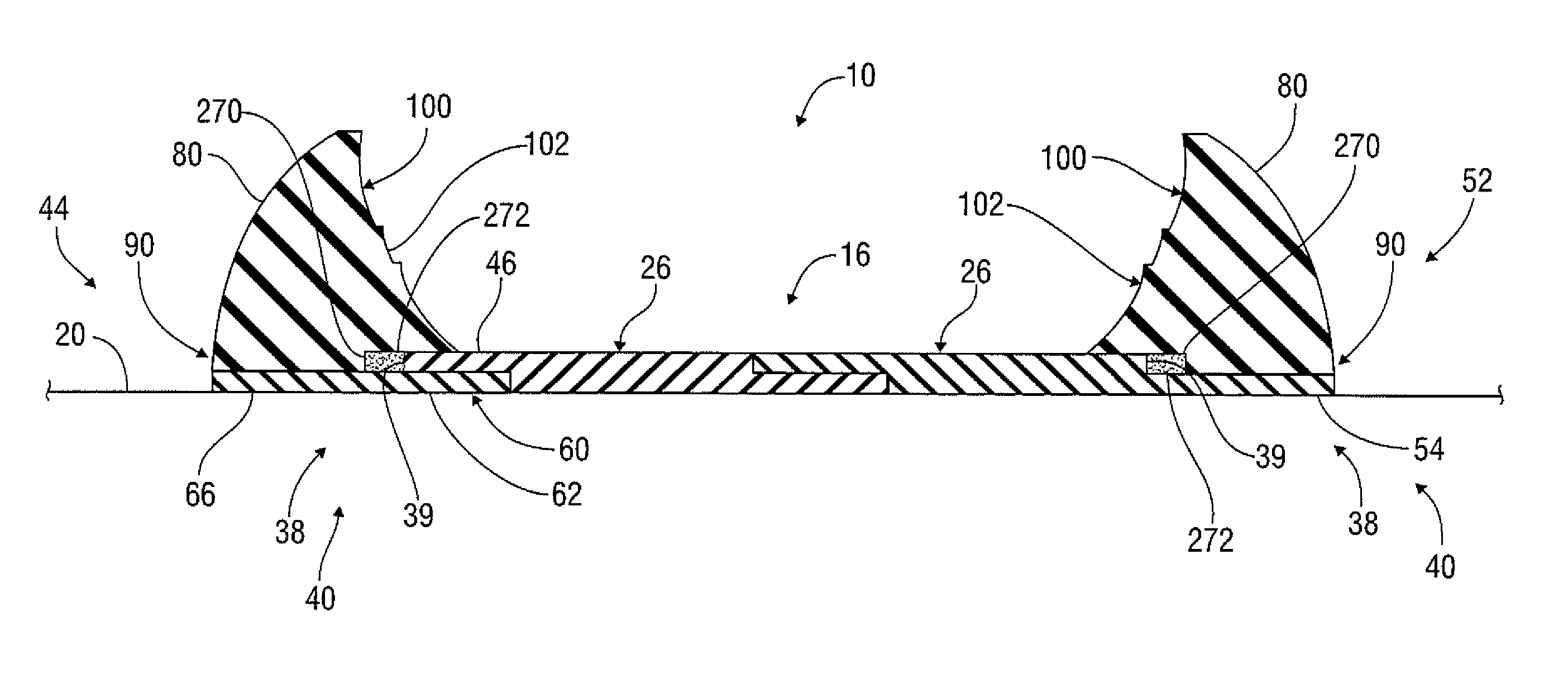
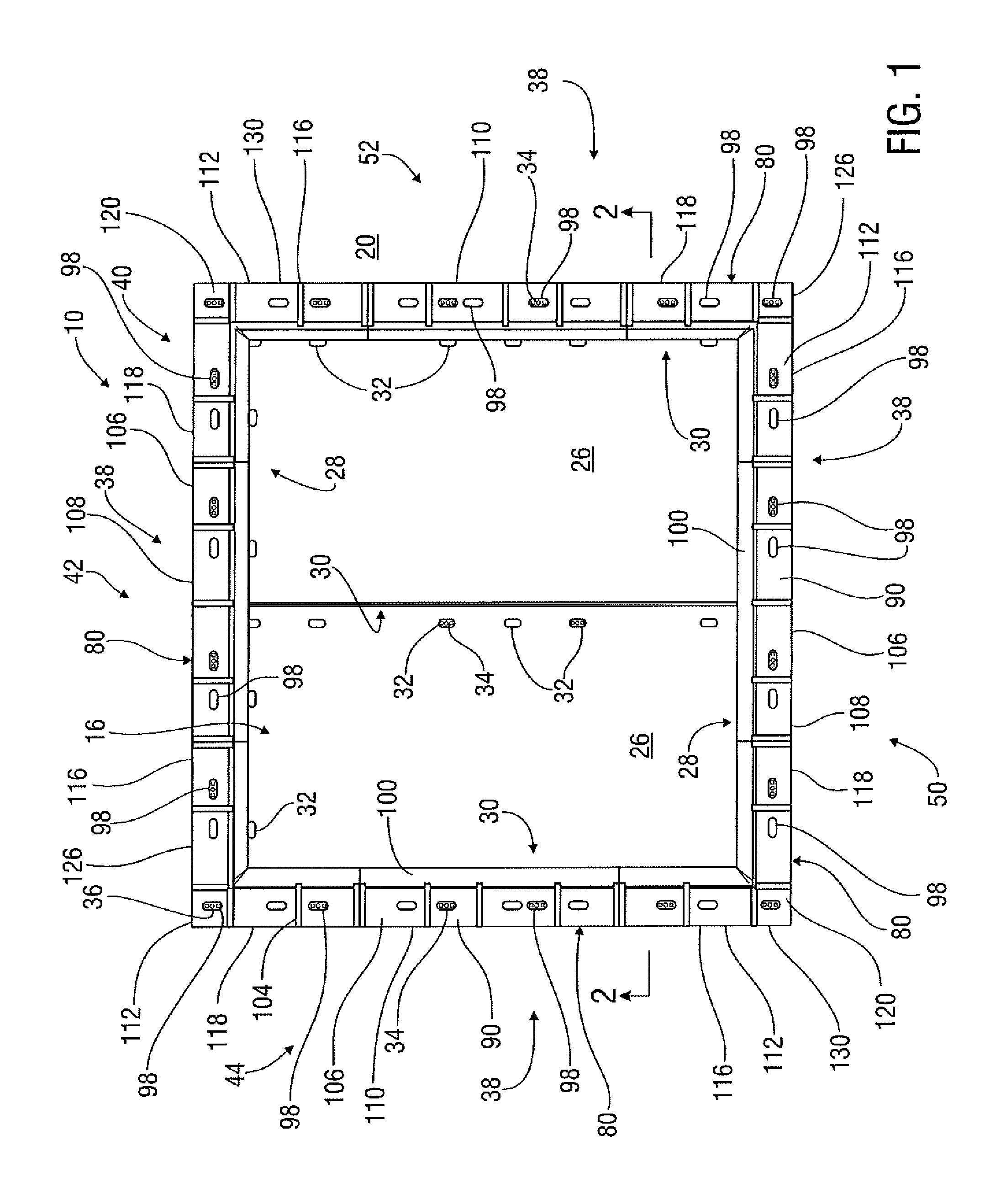
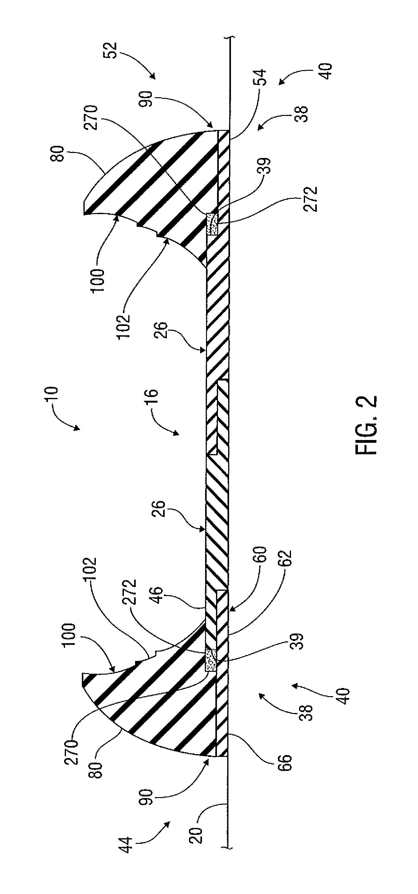
[0032]Characteristics and advantages of the present disclosure and additional features and benefits will be readily apparent to those skilled in the art upon consideration of the following detailed description of exemplary embodiments of the present disclosure and referring to the accompanying figures. It should be understood that the description herein and appended drawings, being of example embodiments, are not intended to limit the claims of this patent or any patent or patent application claiming priority hereto. On the contrary, the intention is to cover all modifications, equivalents and alternatives falling within the spirit and scope of the claims. Many changes may be made to the particular embodiments and details disclosed herein without departing from such spirit and scope.

[0033]In showing and describing preferred embodiments in the appended figures, common or similar elements are referenced with like or identical reference numerals or are apparent from the figures and / or ...


PUM

PropertyMeasurementUnit
heightaaaaaaaaaa
heightaaaaaaaaaa
ninety degree angleaaaaaaaaaa

Abstract

System for containing liquid introduced onto a reusable load-supporting surface includes a plurality of interconnectable berm members configured to releasably sealingly engage the load-supporting surface to prevent leakage of liquid from the load-supporting surface around its perimeter.

Description

FIELD OF THE DISCLOSURE[0001]The present disclosure relates generally to preventing the leakage of liquid from a load-supporting surface and, more particularly, to a liquid containment system.BACKGROUND[0002]Temporary or semi-permanent support surfaces have been used for roadways, remote jobsites, industrial staging areas and the like in an ever-increasing myriad of industries, such as construction, military, oilfield, transportation, disaster response, utilities and entertainment. These support surfaces are often made up of heavy duty, durable, all-weather thermoplastic mats, which are reusable and interlock together to form the support surface. Traditionally, a plastic liner is placed below and around the mat assembly in an effort to capture liquids that are spilled or otherwise introduced onto the support surface before such liquids encounter the subgrade terrain.[0003]The use of liners with temporary or semi-permanent support surfaces may have one or more disadvantages. In many ...

Claims


Application Information

Patent Timeline
Patent Type & Authority Patents(United States)
IPC IPC(8): E02B7/00E01C9/08E01H1/00E02D31/00
CPCE02D31/002E01C9/086E01H1/001B65D90/24B65D90/26E02B8/04H05K999/99
Inventor MCDOWELL, JAMES KERWIN
Owner NEWPARK MATS & INTEGRATED SERVICES
Why Eureka
Try Eureka