Determining and placing spinal implants or prostheses

a technology for spinal implants and prostheses, applied in the field of spinal abnormalities, can solve the problems of inability to detect pain alone through x-ray or scan of patients, no procedure or system has been proposed, and the patient's outcomes vary widely

Active Publication Date: 2015-05-26
NEUBARDT SETH L
View PDF15 Cites 6 Cited by
  • Summary
  • Abstract
  • Description
  • Claims
  • Application Information

AI Technical Summary

Benefits of technology

This patent describes a method to determine and place spinal implants or prostheses based on measuring the change in position of vertebrae at an affected level of a patient's spine from a first position where they report pain to a second position where they report less pain. The method involves selecting one or more implants that are designed to move the spine towards the second position and away from the first position when they are placed at the affected level. Additionally, an inflatable balloon device can be used to move the adjacent vertebrae towards the second position and away from the first position. The overall technical effect of this patent is a more effective and precise method for determining and placing spinal implants or prostheses.

Problems solved by technology

Because any given surgeon's intuition is usually based on his or her training and the fellowship program he or she completed, the current practice of evaluating a patient's spine and identifying implant devices to treat suspected abnormalities is subject to uncertainties and often results in patient outcomes that vary widely.
Moreover, pain alone cannot be detected by way of a patient x-ray or scan.
As far as is known, however, no procedure or system has been proposed wherein an affected level of a patient's spine is scanned while the patient assumes a position of greatest pain or discomfort, and the same level is scanned again after the patient assumes a position of greatest comfort, and wherein the difference between the two positions is quantified to allow an implant device to be identified for maintaining the patient's comfort when the device is placed at the scanned level.

Method used


Image

  • Determining and placing spinal implants or prostheses
  • Determining and placing spinal implants or prostheses
  • Determining and placing spinal implants or prostheses

Examples


example one

EXAMPLE ONE

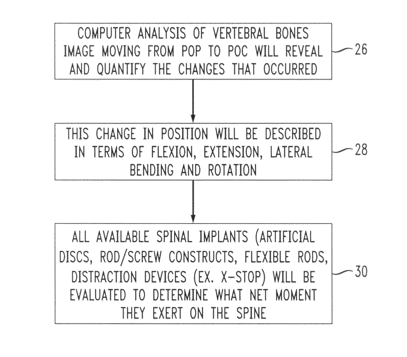
[0039]Patient 1 is positioned and attached to a mobile surgical table 102 such as, e.g., the SpineSix table mentioned above. The patient controls the table 102 to move his / her spine into extremes of flexion, extension, bending, rotation, distraction and compression. The patient then manipulates the table to position their spine in a position where he or she experiences maximum pain (POP). The table position is recorded in terms of degrees of flexion, extension, bending, rotation, distraction and compression.

[0040]FIG. 13 is a radiographic image (plain x-ray) of the patient's spine in the POP, obtained from a scanner 104 in FIG. 12. The image, which may be taken and recorded digitally, is a plain lateral x-ray in which selected angles of lordosis and kyphosis associated with the motion segment are measured. In this example, MRI images are preferred instead of plain x-rays so that anatomical characteristics of the patient's POP and POC can be quantified once the positions ...

example two

[0045]Patient 2 is positioned and attached to the mobile table 102. The patient controls the table 102 to move his / her spine into extremes of flexion, extension, bending, rotation, distraction, and compression. The patient then manipulates the table to a position where he or she experiences maximum pain (POP). The table position is recorded in terms of degrees of spinal flexion, extension, bending, rotation, distraction and compression.

[0046]MRI radiographic lateral and coronal images of the patient's spine in the POP are taken separately by the scanner 104 and recorded. FIG. 18 shows the sagittal (lateral) view of the MRI taken with patient 2 in the POP. The image of FIG. 18 reveals anterior shift of L4 on L5 which is consistent with instability at that level and therefore presumed to be a spinal level of pain. Further, the image shows a posterior shift of L5 on S1 which is consistent with instability at that level and is therefore also presumed to be a spinal level of pain. Accord...


PUM


Abstract

A procedure and system for determining and placing spinal implants or prostheses includes measuring a change in position of vertebrae at an affected level of a patient's spine from a first position where the patient reports greatest pain at the affected level, to a second position where the patient reports least pain at the affected level. Spinal implants or prostheses are selected so as to urge the affected level of the spine toward the second position and away from the first position when the implants are placed at the affected level. In one embodiment, an implant device is formed by one or more inflatable balloons that are placed at determined locations inside a disc space at the affected level. When the balloons are inflated, vertebrae above and below the balloons are urged toward the second position and away from the first position at the affected level.

Description

CROSS REFERENCE TO RELATED APPLICATIONS[0001]This application is a divisional of my U.S. patent application Ser. No. 12 / 898,871 filed Oct. 6, 2010, which is a continuation-in-part (CIP) of my application Ser. No. 12 / 215,097 filed Jun. 25, 2008, and now abandoned. The '097 application claimed priority under 35 U.S.C. §119(e) of my U.S. Provisional Patent Application No. 60 / 937,055 filed Jun. 25, 2007, titled “System for Treatment of Spinal Abnormalities Using Patient Selected Positions”.BACKGROUND OF THE INVENTION[0002]1. Field of the Invention[0003]The present invention concerns treatment of spinal abnormalities by the use of implants or prostheses, and a procedure and system for placing the implants or prostheses.[0004]2. Discussion of the Known Art[0005]Surgeons and clinical practitioners use radiographic tools such as MRI scans and X-rays along with their experience and intuition to evaluate if a patient's spine is within a so-called “normal” configuration. If not, the surgeon de...

Claims


Application Information

Patent Timeline
Patent Type & Authority Patents(United States)
IPC IPC(8): A61B5/05A61B6/00A61B5/00A61B5/055A61B5/107A61B17/02A61B17/88A61B19/00A61F2/30A61F2/44A61F2/46
CPCA61F2/4657A61B5/1077A61B19/46A61B19/50A61F2/441A61F2/442A61B17/8855A61B5/055A61B5/4504A61B5/4514A61B5/4561A61B6/505A61B19/24A61B2017/0256A61B2019/502A61B2019/504A61B2019/505A61B2019/508A61B2019/5236A61B2019/5238A61F2/44A61F2002/3008A61F2002/302A61F2002/30583A61F2002/30586A61F2002/30841A61F2002/30952A61F2210/0085A61F2230/0065A61F2250/0098A61B2034/102A61B2034/104A61B2090/376A61B90/02A61B90/06A61B34/10A61B2034/105A61B2034/108A61B2090/374
Inventor NEUBARDT, SETH L.
Owner NEUBARDT SETH L
Why Eureka
Try Eureka