Liquid ejecting apparatus

a liquid ejector and liquid ejector technology, applied in printing and other directions, can solve the problems of clogging of nozzle openings, affecting the ejector's ejection efficiency, so as to reduce the pressure difference in the manifolds of the plurality of liquid ejectors, prevent the weight of liquid, and reduce the cost

Active Publication Date: 2015-06-02
SEIKO EPSON CORP
View PDF11 Cites 0 Cited by
  • Summary
  • Abstract
  • Description
  • Claims
  • Application Information

AI Technical Summary

Benefits of technology

[0009]An advantage of some aspects of the invention is that the liquid ejecting apparatus that is capable of preventing the weight of ejected liquid droplets from varying depending on the consumption of liquid ejected at a time, and preventing uneven application of the liquid is provided.
[0010]According to an aspect of the invention, a liquid ejecting apparatus includes a liquid ejecting head that ejects liquid in a manifold as liquid droplets from a nozzle opening; a supply path that supplies the liquid to the manifold; a pump unit that is disposed in the supply path and pumps the liquid; and a discharge path that discharges the liquid from the manifold, wherein a flow path resistance of the discharge path from the manifold is smaller than a flow path resistance of the supply path from the pump unit to the manifold. Accordingly, since the flow path resistance of the discharge path is decreased, a pressure in the manifold can be prevented from varying depending on the amount of liquid ejected at a time. As a result, the difference in the weight of ejected liquid can be reduced, thereby preventing uneven application of the liquid. Further, since the liquid is pumped by using the pump unit, the liquid can be supplied under a high pressure.
[0017]It is preferable that the liquid ejecting apparatus further includes a plurality of liquid ejecting heads, wherein the supply path that supplies the liquid from the pump unit to the liquid ejecting head is divided into branches. With this configuration, the liquid can be supplied to a plurality of liquid ejecting heads by using one pump unit, thereby eliminating the need of a plurality of pump units and reducing the cost. Further, a difference in the pressure in the manifolds of the plurality of liquid ejecting heads can be reduced, thereby preventing the weight of liquid ejected from the plurality of liquid ejecting heads from varying.
[0018]It is preferable that pressure adjustment of a liquid meniscus at the nozzle opening is performed by using a water head difference between a liquid ejection surface to which the nozzle opening is open and the liquid storing unit. With this configuration, pressure adjustment can be performed without a negative pressure pump or the like, thereby reducing the cost.

Problems solved by technology

Such an ink jet recording head has a problem of ejection failure such as clogging of nozzle openings due to thickening of ink, sedimentation of ink components and containment of air bubbles.
This causes a pressure change in the manifold and leads to a problem in that the weight of ejected ink droplets varies.
Such a problem is not limited to the ink jet recording apparatuses and exists in the liquid ejecting apparatuses that eject liquid other than ink.

Method used


Image

  • Liquid ejecting apparatus
  • Liquid ejecting apparatus
  • Liquid ejecting apparatus

Examples


first embodiment

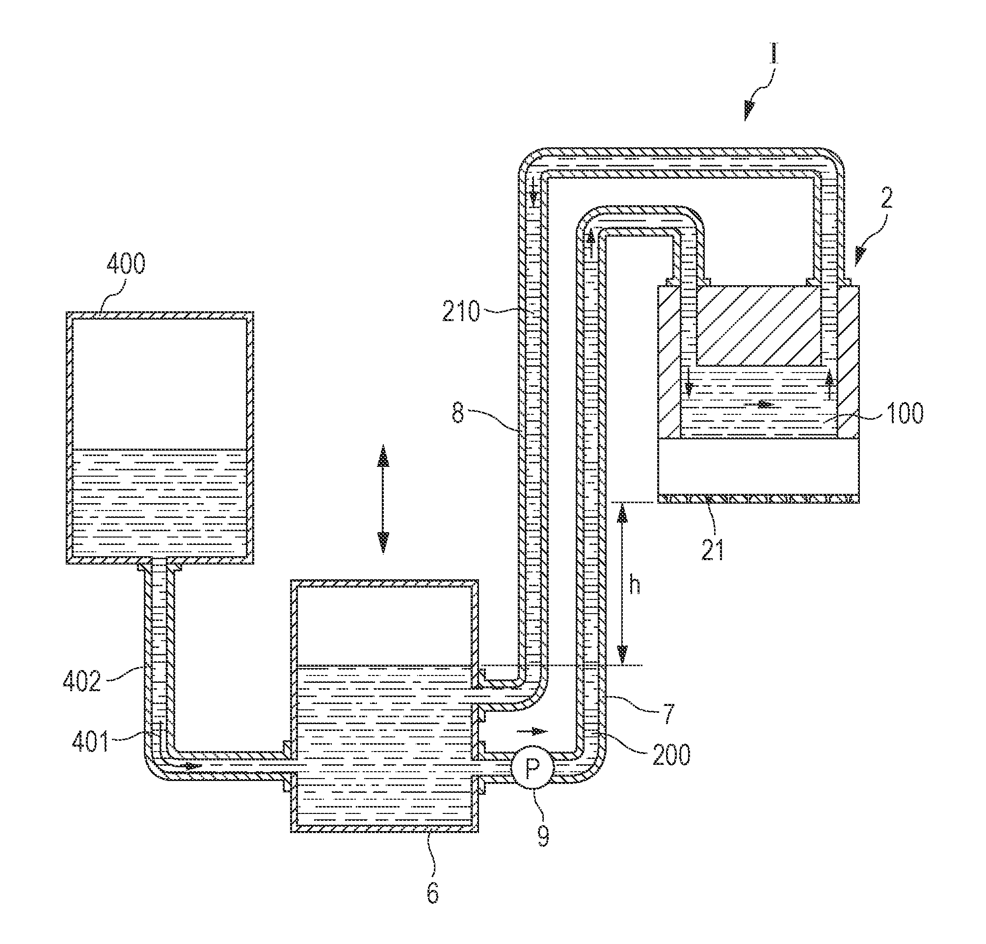
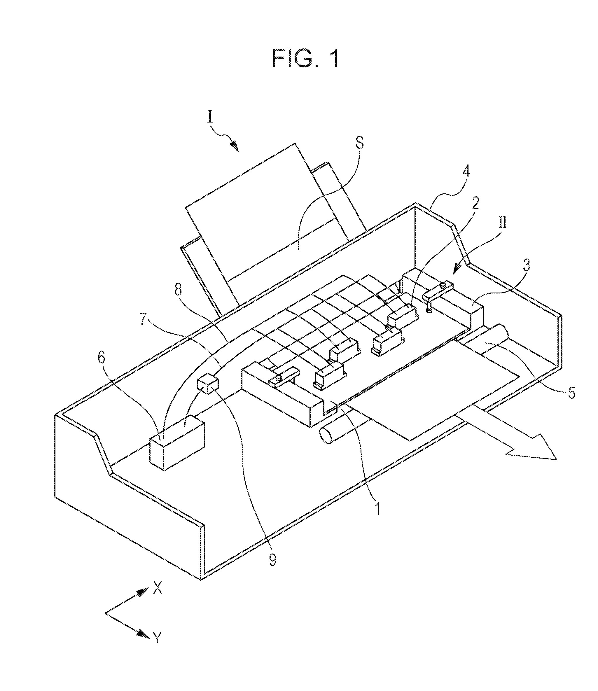
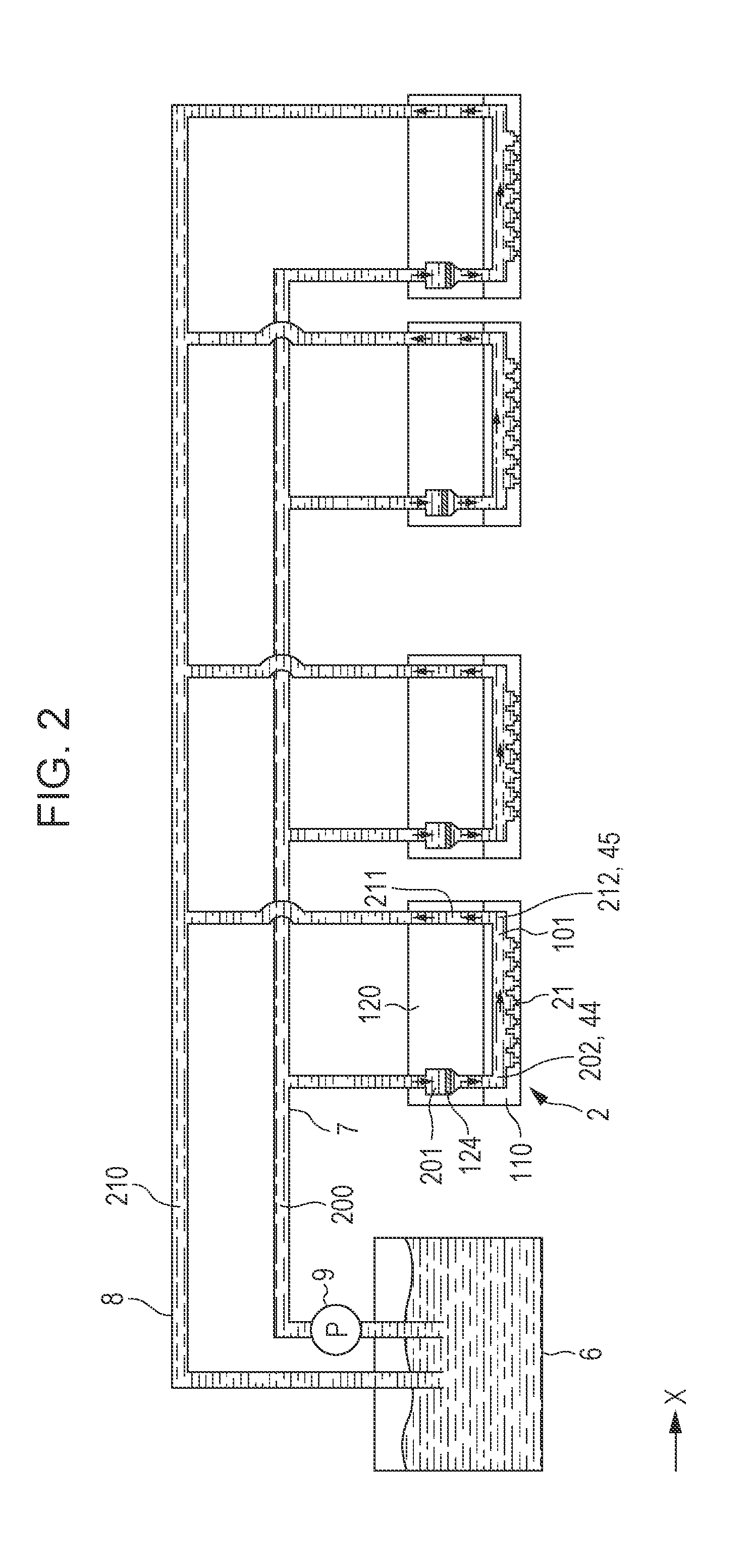
[0031]FIG. 1 is a perspective view which shows a schematic configuration of an ink jet recording apparatus which is an example of liquid ejecting apparatus according to a first embodiment. FIG. 2 is a sectional view which shows a schematic configuration of the ink jet recording apparatus.

[0032]As shown in FIG. 1, an ink jet recording apparatus I which is an example of liquid ejecting apparatus of this embodiment is a so-called line-type ink jet recording apparatus in which a head unit II is fixedly attached on an apparatus body 4 and has a plurality of ink jet recording heads 2 so that printing is performed when a recording medium such as a recording sheet S is transported in a transporting direction.

[0033]The head unit II includes a base plate 1 and the plurality of ink jet recording heads 2 that are held by the base plate 1. A nozzle plate which is an ink ejection surface of the ink jet recording heads 2 is provided on one side of the base plate 1. The base plate 1 is fixedly atta...


PUM


Abstract

A liquid ejecting apparatus includes a liquid ejecting head that ejects liquid in a manifold as liquid droplets from a nozzle opening; a supply path that supplies the liquid to the manifold; a pump unit that is disposed in the supply path and pumps the liquid; and a discharge path that discharges the liquid from the manifold, wherein a flow path resistance of the discharge path from the manifold is smaller than a flow path resistance of the supply path from the pump unit to the manifold.

Description

CROSS REFERENCE TO RELATED APPLICATIONS[0001]This application claims priority to Japanese Patent Application No. 2012-227347 filed on Oct. 12, 2012. The entire disclosure of Japanese Patent Application No. 2012-227347 is incorporated herein by reference.BACKGROUND[0002]1. Technical Field[0003]The present invention relates to liquid ejecting apparatuses having a liquid ejecting head that ejects liquid from nozzle openings, and more specifically to ink jet recording apparatuses having an ink jet recording head that ejects ink as liquid droplets.[0004]2. Related Art[0005]Liquid ejecting apparatuses having a liquid ejecting head that ejects liquid include ink jet recording apparatuses having an ink jet recording head that generates a pressure in flow paths by using pressure generating means and ejects ink droplets from nozzle openings that communicate with the flow paths.[0006]Such an ink jet recording head has a problem of ejection failure such as clogging of nozzle openings due to thi...

Claims


Application Information

Patent Timeline
Patent Type & Authority Patents(United States)
IPC IPC(8): B41J2/175B41J2/18
CPCB41J2/17596B41J2/18B41J2/17563
Inventor OWAKI, HIROSHIGEHAGIWARA, HIROYUKIUEZAWA, HARUHISA
Owner SEIKO EPSON CORP
Why Eureka
Try Eureka