USB charging circuit

a charging circuit and usb technology, applied in the direction of safety/protection circuits, charging a large amount of portable electronic devices that consume different voltages, and arrangement of several simultaneous batteries, can solve the problems of affecting the charging speed, affecting the charging operation, and requiring a large amount of electrical outlets and voltage converters, so as to prolong the life of the usb charging circui

Active Publication Date: 2015-06-02
CHEN-SOURCE INC
View PDF1 Cites 12 Cited by
  • Summary
  • Abstract
  • Description
  • Claims
  • Application Information

AI Technical Summary

Benefits of technology

[0008]The present invention has been accomplished under the circumstances in view. It is the main object of the present invention to provide a USB charging circuit, which eliminates the drawbacks of conventional USB chargers.
[0009]According to one aspect of the present invention, the USB charging circuit comprises a mating hub module, a power supply module, and at least one output control unit. The power supply module uses a synchronization / charge mode switching circuit to detect whether or not an external computer is connected to the USB input port of the mating hub module, and then to output a data transmission synchronization or charge mode judgment signal to the USB charging control circuit of each connected output control unit, triggering the USB charging control circuit to control output of data and power to a respective connected mobile electronic device subject to the nature of the mode judgment signal. Thus, if an external computer is connected, a data synchronization mode is executed. If no external computer is connected, a rapid charging mode is executed. Because the USB charging circuit employs a complete hardware logical judgment technique for output control, saving the cost, enhancing charging speed and achieving synchronous multi-port data transmission operation.
[0011]Further, the USB charging circuit of each output control unit uses a current detector to detect the output current of the associating USB output port and to provide a current signal to a LED control circuit of a status display module. The LED control circuit receives the mode judgment signal outputted by the synchronization / charge mode switching circuit, and controls respective LEDs to give off light subject to the detected current signal and operational mode, enabling the user to understand and monitor the data synchronization or charging status of the portable electronic device that is connected to the respective USB output port.
[0012]Further, each output control unit of the USB charging circuit uses a current detector to detect the output current of the respective USB output port and to provide the detected current signal to an over-current protection circuit. If the current or temperature is excessively high, the over-current protection circuit immediately provides an over-current protection instruction to the associating USB charging control circuit, driving the respective USB charging control circuit into power-off state to make no voltage output, interrupting output of power supply, and protecting the internal components of the connected portable electronic device(s) against a high breakdown voltage or high temperature and prolonging the lifespan of the USB charging circuit and the connected portable electronic device(s).

Problems solved by technology

However, charging a large amount of portable electronic devices that consume different voltages requires a large amount of electrical outlets and voltage converters, complicating the arrangement of power cables and charging systems and the charging operation.
If 500 mA is used to charge a portable electronic device, the charging speed is relatively slow.
It will take a lot of time to charge or update a large amount of portable electronic devices.

Method used


Image

  • USB charging circuit
  • USB charging circuit
  • USB charging circuit

Examples


Embodiment Construction

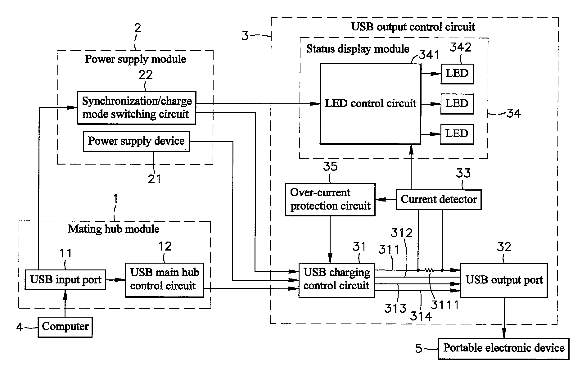
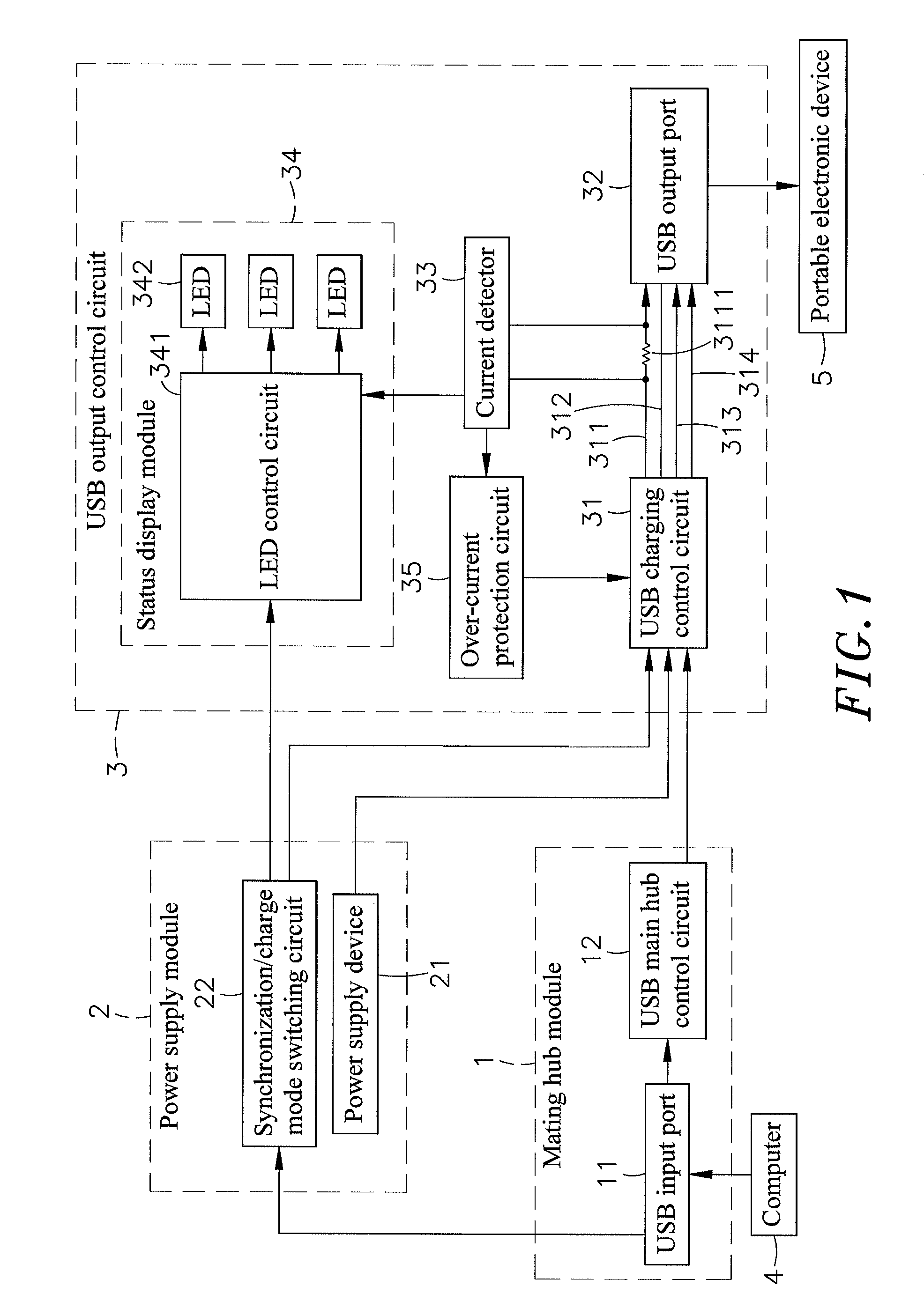
[0015]Referring to FIG. 1, a USB charging circuit in accordance with the present invention is shown. The USB charging circuit comprises a mating hub module 1, a power supply module 2, and at least one output control unit 3.

[0016]The mating hub module 1 comprises a USB input port 11 for receiving a data signal and a power signal (for example, 5V) from an external computer 4, and a USB main hub control circuit 12 electrically connected to the USB input port 11 for receiving the data signal from the USB input port 11.

[0017]The power supply module 2 comprises a power supply device 21, and a synchronization / charge mode switching circuit 22 electrically connected to the USB input port 11 of the mating hub module 1 and adapted to detect the output of the power signal (for example, 5V) out of the USB input port 11 and to output a corresponding mode judgment signal.

[0018]The at least one output control unit 3 each comprises a USB charging control circuit 31 electrically connected to the USB ...


PUM


Abstract

A USB charging circuit includes a mating hub module including a USB input port for the connection of an external computer and a USB main hub control circuit electrically connected to the USB input port, a power supply module including a power supply device and a synchronization / charge mode switching circuit for detecting the power signal output of the USB input port and outputting a corresponding mode judgment signal, and one or multiple output control units each including a USB charging control circuit electrically connected to the USB main hub control circuit, the power supply device and the synchronization / charge mode switching circuit to receive the outputted data signal, power supply and mode judgment signal and a USB output port for receiving the outputted data signal and power supply from the USB charging control circuit so that connected portable electronic devices can be charged or receive data synchronously.

Description

BACKGROUND OF THE INVENTION[0001]1. Field of the Invention[0002]The present invention relates to USB chargers and more particularly, to a USB charging circuit, which uses a synchronization / charge mode switching circuit to detect the connection of an external computer, and a USB charging control circuit to control output of power and data to each connected portable electronic device. The USB charging circuit employs a complete hardware logical judgment technique for output control, saving the cost, enhancing charging speed and achieving synchronous multi-port data transmission operation.[0003]2. Description of the Related Art[0004]With fast development of semiconductor manufacturing process and multimedia information technologies, notebook computers, tablet computers, smart phones, PDAs and many other electronic devices have been created having light, thin, short, small and powerful characteristics. Due to the advantages of small size, light weight, high mobility, high application fl...

Claims


Application Information

Patent Timeline
Patent Type & Authority Patents(United States)
IPC IPC(8): H02J7/00
CPCH02J7/0013H02J7/342H02J7/0047H02J7/00304H02J7/00
Inventor SU, CHING-FANG
Owner CHEN-SOURCE INC
Why Eureka
Try Eureka