Optical detecting device and related method of synchronization adjustment

a technology of optical detecting and synchronization adjustment, applied in the field of optical detecting devices, can solve problems such as drawbacks of expensive costs, and achieve the effect of accurate differentiation

Inactive Publication Date: 2015-06-02
PIXART IMAGING INC
View PDF7 Cites 2 Cited by
  • Summary
  • Abstract
  • Description
  • Claims
  • Application Information

AI Technical Summary

Benefits of technology

[0010]According to the claimed invention, the method further includes decreasing the exposure frequency of the image detector according to predetermined modes when parts of the continued image set do not capture the indicating light source.
[0015]According to the claimed invention, the method further includes increasing the exposure frequency of the image detector when the image detector captures the indicating light source, executing the synchronization adjustment of the exposure timing sequence and the light emitting timing sequence, and decreasing the exposure frequency of the image detector when the exposure timing sequence and the light emitting timing sequence are in synchronization.
[0021]The present invention can determine the phase difference between the image detector and the indicating light source according to the intensity of the continued images, for automatic synchronization adjustment of the optical detecting device, so that the optical detecting device can accurately distinguish whether the stylus with the active luminosity function is located over the screen of the optical touch system, and can calculate the position and the movement of the stylus accordingly.

Problems solved by technology

However, the reference light source includes the extra signal receiver, and has drawbacks of expensive cost.

Method used


Image

  • Optical detecting device and related method of synchronization adjustment
  • Optical detecting device and related method of synchronization adjustment
  • Optical detecting device and related method of synchronization adjustment

Examples


Embodiment Construction

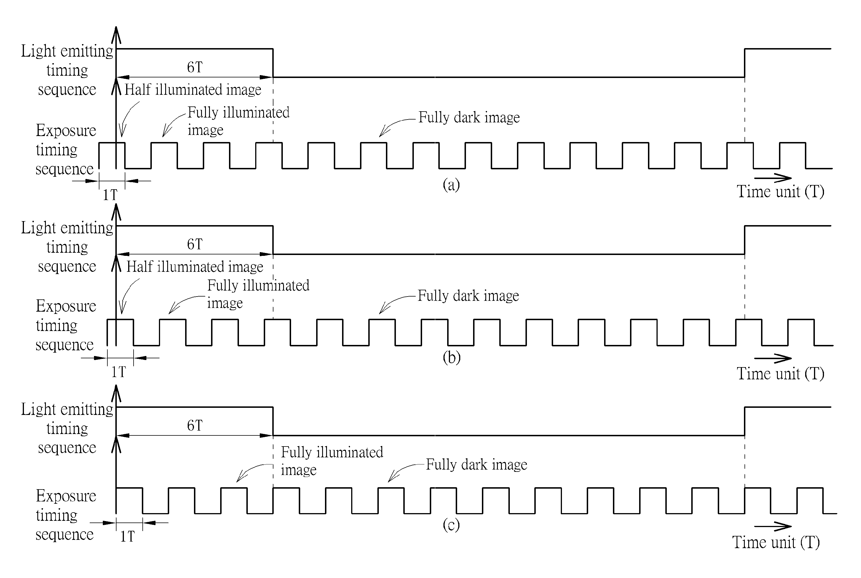
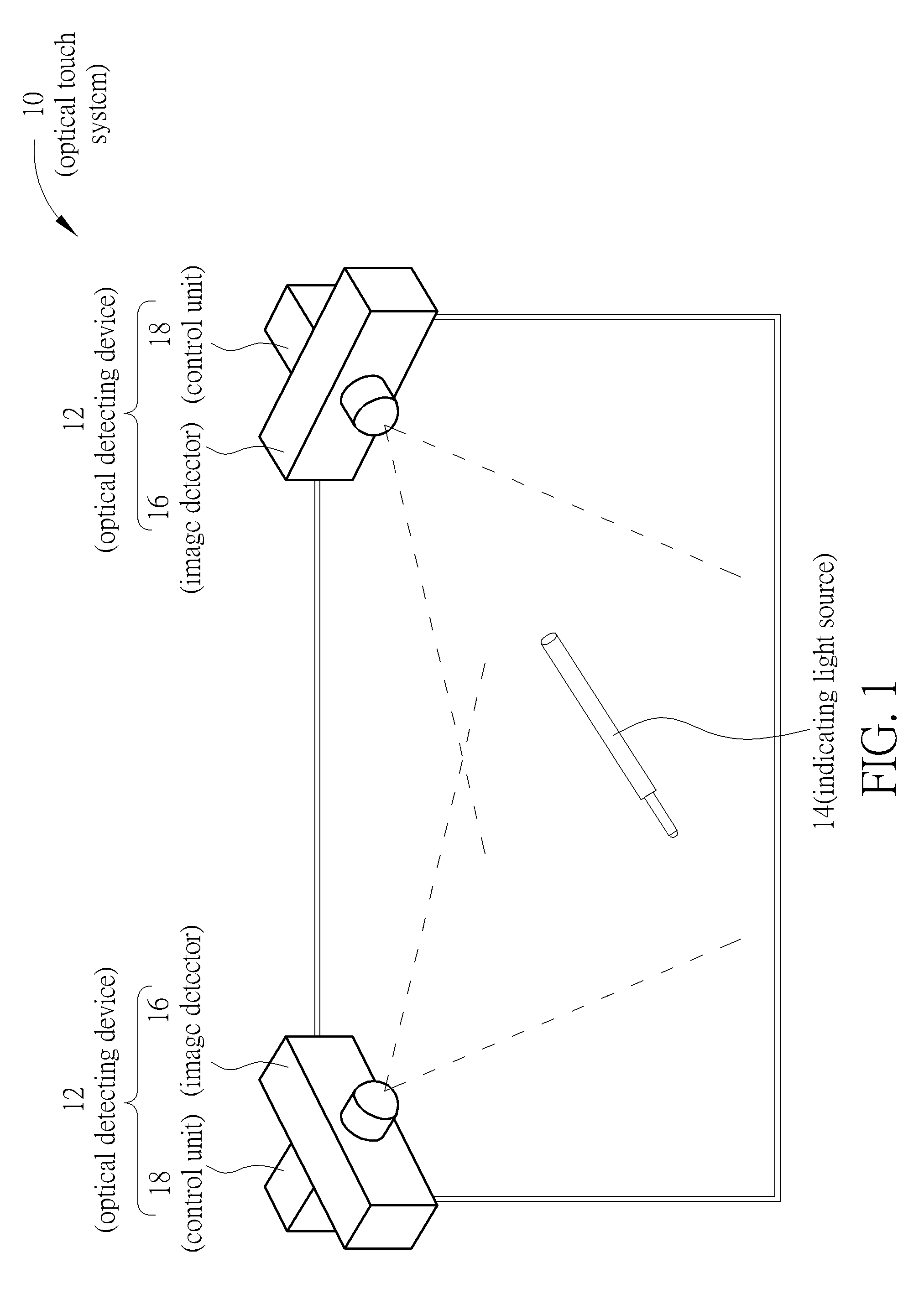
[0030]Please refer to FIG. 1. FIG. 1 is a diagram of an optical touch system 10 according to an embodiment of the present invention. The optical touch system 10 includes an optical detecting device 12 and an indicating light source 14. The optical detecting device 12 can detect and trace intensity and movement of an optical signal from the indicating light source 14, so as to determine a control command inputted by the user via the indicating light source 14. The indicating light source 14 can be a stylus with active luminosity function. The optical detecting device 12 includes an image detector 16 and a control unit 18. The image detector 16 is disposed on corners of the screen of the optical touch system 10, and faces toward the screen to acquire a continued image set. The screen may have no reflector, or further may be laid by optical absorbent for providing uniformly dark background. The image detector 16 can detect variation of the optical signal outputted by the indicating lig...


PUM


Abstract

A method of synchronization adjustment is applied to an optical detecting device, so as to synchronize an exposure timing sequence of an image detector with a light emitting timing sequence of an indicating light source. The method includes acquiring a continued image set, analyzing intensity of each image of the continued image set, and adjusting the exposure timing sequence according to duty cycle of the image detector and intensity ratio of at least two images. An exposure frequency of the image detector is greater than a flickering frequency of the indicating light source.

Description

BACKGROUND OF THE INVENTION[0001]1. Field of the Invention[0002]The present invention relates to an optical detecting device, and more particularly, to an optical detecting device capable of tracing a light emitting timing sequence of an active reference light source and a related method of synchronization adjustment.[0003]2. Description of the Prior Art[0004]For eliminating effect of background noise, a conventional optical detecting device utilizes a reference light source with specific light emitting frequency to filter the background noise. The light emitting frequency of the reference light source is varied due to low energy of the built-in battery. Two conventional detection methods, such as synchronous flickering detection and asynchronous flickering detection, can be applied to the image detector for accurately acquiring the reference light source with the specific light emitting frequency. The conventional detection methods are set according to comparison between the exposu...

Claims


Application Information

Patent Timeline
Patent Type & Authority Patents(United States)
IPC IPC(8): H04N1/04H04N1/028
CPCH04N1/02815H04N1/40056G06F3/042G06F3/03542G06F3/04162H04N23/745H04N23/73
Inventor KAO, MING-TSANCHENG, HSIN-CHIKO, YI-HSIEN
Owner PIXART IMAGING INC
Why Eureka
Try Eureka